Dishwasher Motor 3 phase star, triple coil construction - how to run?

nsaspook

Joined Aug 27, 2009
16,468
..
I'm an old school guy. I want to take a chip and make it do something. Not an attiny or some other µP. I don't know how to code, I don't have things to use for coding, Coding is strange to me, I even kind of fear it. I am what I am.
Coding, as taught in the modern software priesthood, is strange and too abstracted. Embedded programming controllers is as old school hardware related as solder, flux, TTL and CMOS. Don't fear it, take the time to learn it, you will not regret the time spent..
 

MaxHeadRoom

Joined Jul 18, 2013
30,776
. Some have said it's a BLDC with hall effect sensors. I balked at that because it doesn't have any hall effect sensors. I'm not balking at the idea of it being brushless.
That was my mistake, but they are both identically constructed motors, one has commutation detection devices and the other uses an electronic method to detect the pole position, this is commonly called an ECM (electronically commutated motor) which are now common in HVAC and many other applications.
The BLDC version, although an identical motor to the AC 3ph version, the difference lies in the type of power applied.
The BLDC is also electronically commutated and is so named because it only has two windings powered at any one time, and resembles a DC brushed motor, turned inside-out. ;)
 

Thread Starter

Tonyr1084

Joined Sep 24, 2015
9,744
A BLDC is a PMSM 3-phase AC motor. Each type is designed internally to optimize the performance from the expected drive waveform. It's not a stepper motor.
PMSM is a term I don't recognize. If I take a guess I'd say "Permanent Magnet SOMETHING Motor" Would someone please clarify PMSM?
 

Thread Starter

Tonyr1084

Joined Sep 24, 2015
9,744
one has commutation detection devices and the other uses an electronic method to detect the pole position
I think I understand the second method "electronic method to detect the pole position" but am not making the connection of how the other (the first mentioned) "has commutation detection devices". Wouldn't that require some sort of feedback? Hence more wires? Honestly I'm trying to understand but sometimes my mental blocks get in the way like lego's on the floor in the dark hallway during the wee hours of the morning.
 

MaxHeadRoom

Joined Jul 18, 2013
30,776
I think I understand the second method "electronic method to detect the pole position" but am not making the connection of how the other (the first mentioned) "has commutation detection devices". Wouldn't that require some sort of feedback? Hence more wires? Honestly I'm trying to understand but sometimes my mental blocks get in the way like lego's on the floor in the dark hallway during the wee hours of the morning.
What the controller board does is exercise the motor briefly at start up in order to find out/detect the various pole positions of the rotor.
Once it knows this, it can synchronize the applied frequency to the actual pole position when under run operation.
The BLDC feedback used to be done with three 'Hall effect' sensors, now often optical means are used, which are more accurate.
Your motor appears 'sensorless' version.
 

MaxHeadRoom

Joined Jul 18, 2013
30,776
Just hooked the impeller to my drill and spun it at full speed. Saw 21VAC. On the scope I saw a beautiful sine wave. I don't see any sign of sensors. Bottom line, what I have (I think) is a 3 phase 24VAC motor. I said I THINK!

Double trace video - I can upload it to YT but I managed a screen grab where you can see one and a half traces with a ghost of a trace the camera didn't quite capture.
View attachment 293905
Each trace is of a different set of coils. Let me know if you want me to grab a single set of coils and their common point.
BTW, if you want to 'see' each phase only, and you don't have access to the Star point, what you need to do is set up a virtual neutral, this is done by connecting three 1k resistors to each phase, the other resistor ends are connected together.
Use the res common point as the virtual neutral to any one phase, if double beam, you can see two phases.
This method is also used to align an encoder on the motor shaft that possesses commutation pulses.
 

Attachments

nsaspook

Joined Aug 27, 2009
16,468
I think I understand the second method "electronic method to detect the pole position" but am not making the connection of how the other (the first mentioned) "has commutation detection devices". Wouldn't that require some sort of feedback? Hence more wires? Honestly I'm trying to understand but sometimes my mental blocks get in the way like lego's on the floor in the dark hallway during the wee hours of the morning.

The for the "electronic method to detect the pole position" the commutation detection device can be the laws of induction (back EMF) used as feedback on the coil driver wiring for sensor-less commutation.
http://ww1.microchip.com/downloads/en/AppNotes/00885a.pdf
WHAT IS BACK EMF? When a BLDC motor rotates, each winding generates a voltage known as back Electromotive Force or back EMF, which opposes the main voltage supplied to the windings according to Lenz’s Law. The polarity of this back EMF is in opposite direction of the energized voltage. Back EMF depends mainly on three factors: • Angular velocity of the rotor • Magnetic field generated by rotor magnets • The number of turns in the stator winding
1683825399502.png
https://www.digikey.com/en/articles/controlling-sensorless-bldc-motors-via-back-emf
 

Thread Starter

Tonyr1084

Joined Sep 24, 2015
9,744
After reading that last post by nsaspook it looks like a better option would be to figure out how they're running the motor. Obviously they've done all the work. All I need to figure out is how they're running it.

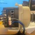
The motor has been reassembled (two screws). It would seem obvious that the two blue wires provide run power. The three smaller grey wires (no distinguishing markings) do something to control the motor. Since it's a simple pump I'll assume they have no desire to run it backwards. There may be different speed settings for different wash conditions - but I guess at that. The machine has long been replaced. Not even sure which manufacturer used the pump. The machine was replaced because it kept going through control boards. I have two of them still hanging around for scrap purposes.

1683830993254.png
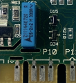
I would be guessing but I think it was connector location P10. The controllers I have are 2009 Whirlpool products, so maybe that means something. Nevertheless, the three grey wires do something. The connector (P10), the center pin has its trace on the back side of the board. It appears that the right most pin goes to both D15 and Q34. The left most pin goes off somewhere else. The center pin (on the back side - outlined in blue) goes to D15 via the feedthrough. It also goes to R210 (don't know if I removed that resistor, gone on the other board too); and it goes off to elsewhere. This is not a complete diagram, and I wouldn't know which grey wire went where - OR if it even went to this location. It appears P10 may have been a 4 pin connector. But the pin off to the left on its own appears to go off to other connector pins (back side).
1683833204179.png1683833259194.png

The populated board has not been scavenged for parts while the lighter green board has been. Back-lighting shows the traces.

I don't expect miracles here, just maybe someone might know something about this silly motor. What with BEMF and timing and all that - making something to run the board seems beyond my skill level. I just wish I still had the wiring diagram for the machine. I'll look on line and see if I can spot something familiar, but this has been in my scrap bin for several years.
 

MaxHeadRoom

Joined Jul 18, 2013
30,776
After reading that last post by nsaspook it looks like a better option would be to figure out how they're running the motor. Obviously they've done all the work. All I need to figure out is how they're running it.
Have you determined if the motor has on board electronics inside?
This is usually the case with HVAC etc applications, the motor is fed with AC 120v etc and the inside electronics take care of the commutation. and speed control,
I am wondering of the 3 grey are used for some kind of monitoring?
One other alternative is that the 3 grey end up to the 3 motor winding connection and the two blue are sensor feed back.
 

Thread Starter

Tonyr1084

Joined Sep 24, 2015
9,744
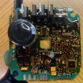
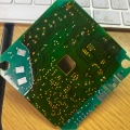
Yes, there IS on-board circuitry in the motor housing.
1683841082635.png . . 1683841150734.png
On the connector (bottom edge of PCB) there is a left contact that is not used. The next two are the blue wires and the last three (right) are for the three grey wires.
 
Last edited:

Thread Starter

Tonyr1084

Joined Sep 24, 2015
9,744
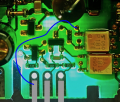
Here's an image of the three grey wire contact points. The blue line shows where the left most pin goes.
1683842726528.png
The two transistor like devices are marked W 18 and a sideways PO. Have no idea of the manufacturer and haven't looked up those codes in ages. 's all I gots.
 
Top