Discrete Pulse Width Modulator

Thread Starter

iimagine

Joined Dec 20, 2010
511
Sure, although I have developed a more efficient circuit, If you are interested I will post it.

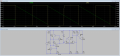
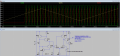
Here is how it works: Q1-Q4 are used to generate a linear ramp; Q5+Q6 forms an emitter buffer stage; Q7 + Q5 forms a longtail pair and is used as a comparator; Q8 + Q9 is the output stage
 

wayneh

Joined Sep 9, 2010
17,496
It might be nice to show how well it works, i.e. show what range of percent you can obtain. For instance is it 5-95% or full 0-100%. The frequency of operation is also a critical parameter folks need to know.

If you actually build one and play with it, you should submit it to the completed projects section.
 

Thread Starter

iimagine

Joined Dec 20, 2010
511
Here is the updated version with graphs and some info

I'm planning to build this soon as I have the time and will post it

Edit: I know for a fact that my linear ramp gen does work, I have built and tested it. So its just a matter of 'tweaking' the comparator
 

Attachments

Last edited:

Thread Starter

iimagine

Joined Dec 20, 2010
511
Well, here are the test results from the latest version breadboarded. Not too clean, needs a little 'tweaking' but worked on the first try! :)

I used 2n4401/2n4403 for all transistors; R7/R8 voltage divider was replaced with a 500k pot

Next, I will build a Color Organ using this circuit to drive LEDs :D

Please, as always, I would really appreciate any comments on what you think of it and any suggestions to further improve it.

PS: Since it was breadboarded, the freq was not too stable.
 

Attachments

RichardO

Joined May 4, 2013
2,270
PS: Since it was breadboarded, the freq was not too stable.
Just because it is on a breadboard (a solderless one, I suppose) does not make it unstable. I have built many function generator circuits with sine, square and triangle waveforms. Some work as high as 20 MHz and they are stable and predictable.

Can you post a picture of how your prototype looks looks?
 

RichardO

Joined May 4, 2013
2,270
Maybe a little hysteresis would stabilize the comparator?

Good advice. I should have looked at your waveforms before posting the previous comments.

I would still be interested in pictures of your prototype, though. :)
 

Thread Starter

iimagine

Joined Dec 20, 2010
511
I have pics of my prototypes; breadboard and protoboard :)

How do I upload these pics? they are too large! approx 2meg per pic.

I was in the middle of constructing it on the protoboard when I got a suggestion from ronv, It was too late to make any changes so I went ahead and completed it, I will post read outs from this protoboard tomorrow, right now it is working good as an LED dimmer :)
 
Top