 Facebook
 Google
 GitHub
 Linkedin
OK, that all makes sense, thank you!You can by first stopping trying everything under the sun. Mixing boards, 1kΩ resistors, various voltages, etc…
…And design or accept the design of a board or system that works for your specific case.
To design what you need, we need to know how many hours you’d like it to run??? I’ll just assume your power source is 2500mAh.
14 leds at 15mA requires almost 3A. With a 2500mAh source, the LEDs will run for less than an With 2 9V common batteries, it would run for ~30 minutes. If you were to parallel the AA batteries in two sets of 4, you’d still have 6.0 volts and 5,000mAh, which would run for ~1h20m.
The board was designed for a narrow circumstance. Certain LEDs. Certain power input. And you’re trying to muck around with those values and as you’ve seen, it doesn’t always work like you want. I’d put the board aside!
I’m assuming a power pack of 4 AA batteries which will provide 6.0V. Connect the - terminal to the negative lead of all the LED lights. Connect the positive terminal to one side of 14 220Ω resistors*. Connect the other side of each resistor to each of the LED lights. One resistor: one LED.
Re: my re: * note. I got 220 by using the formula I mentioned earlier. I had to adjust my choice because 186Ω is not a standard value. 220 is. I used 3.2 V for the LED because that’s what usually a white LED has as it’s forward voltage (Vf). And per the specs it runs on 0.015A.
R = (Vs-Vf)/(current)R = (6,0-3.2) / 0.015R = 2,8 / 0.015R = 186Ω = ~220ΩI know, that’s a lot of math. But it’s the foundation for what you’re trying to do. LEDs run at various levels of current. From 7mA to 20mA. That’s why different resistor values work (and where the “just use a 1kΩ resistor” came from)
You can temporarily wire up various resistor from 2.2 Ω to 3.0 kΩ. The SMD light will go from very bright white to a dimmer yellow light. That’s what I did for my model rr layout. I run at 12V. Interior apartments and hallways use a 2.2kΩ resistor. Exterior lights and signs plus storefronts just use the included resistor.
I don’t have your LED lights to test my calculation. So you’ll have to try various resistors. You could even customize each light of the diorama individually by doing this. If you want to go crazy, use a miniature 3kΩ potentiometer inline with a 230 Ω resistor to give you fine control of each light!
Diorama LED lighting
- Thread starter Doane2u
- Start date
Scroll to continue with content
djsfantasi
- Joined Apr 11, 2010
- 9,237
Can’t trust the calculator. You’re right!No, it requires 210 mA. About 10 hours operation from AA cells. And if you are right about wanting them dim, they probably need a lot less than that.
I do appreciate all the help from all of you. You obviously are all electronic geeks, I’m not, so please don’t take offense if I ask a few more questions that may sound stupid to you. My goal is for the longest lighting time of a maximum of 15 of the SMD LED 0402 lights I mentioned and for their safest longest life as they would be difficult to replace.
With this criteria:
To not use a wall power supply wort anymore as it's inconvenient.
To not use the controller boards as suggested by many of you
To use some sort of battery pack(s) with covers. I have 1 AA 8 pack (12v), 8x C 2 packs (3v ea),
I have room for several of the C 2 packs (3v) and I can get C 3 packs (4.5v) if that's better, or any other AA or C packs with covers will fit.
To use a resistor in series with each LED, maybe 1k ohm (I never said I was opposed to this, I just didn't know it was necessary)
I can vary the resistor sizes for brightness as suggested or even use a pot.
I have a bunch of 12 out screw type distribution blocks I can use
I think djsfantasi basically answered this just above in #57 but I want to be sure I'm doing this right.
So what do you all think would be the best setup?
Thank you
Except his math was off by a factor of about 30, so don’t go by that.I think djsfantasi basically answered this just above in #57 but I want to be sure I'm doing this right.
Here is what I would do:
1. Use a battery of 6V or more plus a pot. Adjust the pot to get the brightness you want under the lighting conditions expected on a single LED.
2. Measure the the voltage across the pot (call that Vp) and across the LED (call that Vf.)
3. Remove the pot from the circuit and, without changing its setting, and measure the resistance of the pot. Call that Rp.
4. Calculate the current from I = Vp / Rp.
You now have all the information you need for us to help you assess how long each battery option will last.
djsfantasi
- Joined Apr 11, 2010
- 9,237
Get one 220Ω resistor. Wire a battery pack giving you 6VDC, a 220Ω resistor and one LED (with correct polarity) to see that it lights the way you want.I do appreciate all the help from all of you. You obviously are all electronic geeks, I’m not, so please don’t take offense if I ask a few more questions that may sound stupid to you. My goal is for the longest lighting time of a maximum of 15 of the SMD LED 0402 lights I mentioned and for their safest longest life as they would be difficult to replace.
With this criteria:
To not use a wall power supply wort anymore as it's inconvenient.
To not use the controller boards as suggested by many of you
To use some sort of battery pack(s) with covers. I have 1 AA 8 pack (12v), 8x C 2 packs (3v ea),
I have room for several of the C 2 packs (3v) and I can get C 3 packs (4.5v) if that's better, or any other AA or C packs with covers will fit.
To use a resistor in series with each LED, maybe 1k ohm (I never said I was opposed to this, I just didn't know it was necessary)
I can vary the resistor sizes for brightness as suggested or even use a pot.
I have a bunch of 12 out screw type distribution blocks I can use
I think djsfantasi basically answered this just above in #57 but I want to be sure I'm doing this right.
So what do you all think would be the best setup?
Thank you
Optional: Try the above with a 470Ω, 1kΩ, and 2kΩ resistors and pick the look/ resistance that you want.
Wire two 4 C cell battery packs in parallel. Connect all of the resistors to one connection and all of the proper polarity LED leads to the other connection. Wire the remaining LED lead to the other end of the resistors - one LED to a resistor!
You can insert a power switch inline with one of the combined power leads.
Buy something to organize all of the connections. A prototype circuit board for example. Cut excess resistor leads off once soldered so there is no possibility of a short. Make sure all joints are separated or insulated for the same reason.
djsfantasi
- Joined Apr 11, 2010
- 9,237
Oops, where was my mistake so I don’t do it again?Except his math was off by a factor of about 30, so don’t go by that.
I am reluctant to weigh in here and increase confusion which is why I have been quiet.
I am going to explain some things, express an opinion, and suggest one more possible method—then leave it up to you to decide which way to go. Please try to read this even though it seems very technical. It’s not exceptionally difficult stuff and I am more than happy to answer any questions. Don’t let the learning curve stop you, I promise that with less effort that you expect you will be able to understand it enough to solve many of your own problems with the electronics you need for your projects.
When you attach a resistor to an LED in cases like yours, it is called a current limiting resistor. The reason it’s needed is because LEDs are current driven devices. That is, the LED needs enough voltage to satisfy the \( \mathsf{V_f} \) (Forward Voltage) requirement to get it to conduct*, it is the current that will determine how bright it is.
*while this is true for the rated current and light output of the LED, in practice leakage currents will light the LED faintly at amazingly low voltages.
LEDs will increasingly dissipate current until they burn themselves up, so if the power source is greater than the \( \mathsf{V_f} \) that will cause maximum current consumption (that is, maximum based on the manufacturers specifications for normal operation), so putting a resistor in series well limit the current by dropping the voltage and stop the LED from releasing the magic smoke that makes it work.
All of this can be worked out using Ohm’s Law, a simple three term equation that describes the relationship among voltage, current, and resistance.
A nice trick is to draw a triangle and put the three terms in it with V on top, and IR on the bottom. Then draw a line between the V and the IR horizontally, like so:

now, to figure out which version of the formula to use, cover the unknown term and read what is left. For example, if you want to find E, covering it leaves “I R”, so E = I x R, to find I, cover it and read I = E / R, etc. This way you only have to remember this picture to easily know which formula to use.
So looking at Ohm’s Law, you can see that since I = V / R, increasing R will decrease I, and increasing V will increase I. We can say that current is directly proportional to voltage and inversely proportional to resistance. That’s why putting a resistor in series limits the current.
And this is a very normal and appropriate way to protect the LED and ensure the brightness is what you want—but is has a downside that is relevant for your use. A resistor accomplishes the current limiting by dropping the voltage across itself. The voltage before and after the resistor will be different, because some of that voltage is being turned into heat by the resistor.
The voltage times the current is the power being used. It is measured in Watts (W = V x A). We can do various electronic tricks to trade off voltage for current and vice versa but we can never exceed the total power in Watts that we have to work with. So, for example, 10V at 10A = 100W, and we can do things to make the V and A parts anything we want that adds up to 100W.
But we can’t the fact that no system is 100% efficient. This means that anything we do to make this conversion is going to “cost” something, so we don’t actually have a budget of 100W to work with since paying for the conversion comes out of the same “account”. Various methods offer various efficiencies, from very poor throwing away half the power or more, to very good providing 80%+ of the original power.
So let’s say we have the 10V at 10A and want to power something that needs just 1A. If we choose to go the resistor route, we can work out what size the resistor needs to be if we know the resistance of the load, to which we will have to add more resistance to limit the current.
So, let’s say in this case the load is 10Ω. Using Ohm’s law we can work out how much current will flow at 10V:
There’s another time when we’d also choose a different method, one that doesn’t use power just to heat resistors—when power is very expensive. This might be measured in dollars, but in this case we are talking about a energy budget that determines how “costly” power is. That budget is the amount of energy you have in your battery.
Since one of your goals is maximum battery life, considering the waste as heat in the resistors is important. You can calculate how much of your power will be consumed not lighting your LEDs, and how much runtime you might add using a different method. And that’s what I wanted to recommend. It is certainly not a cheap as resistors, nor as simple (though it is not extremely complicated either!)
I am going to recommend that you use two very small modules. A module is a PCB (Printed Circuit Board) that has an IC or ICs which would normally be incorporated into a larger PCB, along with the required passives (e.g.: capacitors, resistors, inductors, etc.) and a simple connection interface so you can use the chip in your own project without having to design a PCB yourself.
The two modules are a buck converter and a constant current LED driver. The buck converter is a much more efficient way to reduce a voltage. It uses a method involving switching the output on and off very quickly, so it appears to be ordinary DC, but at a lower voltage than the input. It is not 100% efficient, but it doesn’t depend on throwing away power as heat to get the job done.
They are cheap, and can be very small. A recommended example is this one.
 It’s adjustable and can be run from any DC power supply between 4.75 and 23V. The output is adjustable between 1 and 17V (depending on the input) and it will produce the 3A you might need (though I am not sure that you will be running the LEDs that hot). The idea would be to adjust the output so it is very close to the voltage needed to produce enough current for the LEDs, then use this driver module to provide a constant current source.

The module is very small, and adjustable. It can provide up to an amp of constant current so you might need two or three with the LEDs divided among them. The trimmer (variable resistor) on the board sets the current, so is is effectively a dimmer. It also has an enable pin which can be used to turn the LEDs on and off, or to dim them using PWM (Pulse Width Modulation), a topic for another post.
The two of these together would make a simple and efficient arrangement, it would simplify construction by eliminating the need to include a resistor for each LED, and could greatly increase the battery life. I would use a ≥6V supply, and still advocate for the USB PD arrangement I suggested at first, with a 9V trigger board and a cheap USB PD powerbank, or the two-cell 18650 board I also linked to.
So, I said my thing, and now I will leave it to you to decide how you want to go. This is what I would do in your place, but if you choose the resistor route, it will work, and there is nothing really wrong with it. I just think this is better and I don’t think it is over your head to accomplish.
Good luck whatever you choose.
[ EDITED to fix a missed editing mistake and add a clarification, no substantive content changes ]
I am going to explain some things, express an opinion, and suggest one more possible method—then leave it up to you to decide which way to go. Please try to read this even though it seems very technical. It’s not exceptionally difficult stuff and I am more than happy to answer any questions. Don’t let the learning curve stop you, I promise that with less effort that you expect you will be able to understand it enough to solve many of your own problems with the electronics you need for your projects.
When you attach a resistor to an LED in cases like yours, it is called a current limiting resistor. The reason it’s needed is because LEDs are current driven devices. That is, the LED needs enough voltage to satisfy the \( \mathsf{V_f} \) (Forward Voltage) requirement to get it to conduct*, it is the current that will determine how bright it is.
*while this is true for the rated current and light output of the LED, in practice leakage currents will light the LED faintly at amazingly low voltages.
LEDs will increasingly dissipate current until they burn themselves up, so if the power source is greater than the \( \mathsf{V_f} \) that will cause maximum current consumption (that is, maximum based on the manufacturers specifications for normal operation), so putting a resistor in series well limit the current by dropping the voltage and stop the LED from releasing the magic smoke that makes it work.
All of this can be worked out using Ohm’s Law, a simple three term equation that describes the relationship among voltage, current, and resistance.
\[ \mathsf{V=I \times R\space} \space \space \space \space \space or \space \space \space \space \space \space \mathsf{I ={V \over{ R }}} \space \space \space \space \space \space or \space\space \space \space \space \space \mathsf{R = {V\over{ I }}} \]
in the equation, V is voltage, in Volts (though it will sometimes be E), I is for current in Amps, and R is for resistance, in Ohms (Ω)
in the equation, V is voltage, in Volts (though it will sometimes be E), I is for current in Amps, and R is for resistance, in Ohms (Ω)
A nice trick is to draw a triangle and put the three terms in it with V on top, and IR on the bottom. Then draw a line between the V and the IR horizontally, like so:
So looking at Ohm’s Law, you can see that since I = V / R, increasing R will decrease I, and increasing V will increase I. We can say that current is directly proportional to voltage and inversely proportional to resistance. That’s why putting a resistor in series limits the current.
And this is a very normal and appropriate way to protect the LED and ensure the brightness is what you want—but is has a downside that is relevant for your use. A resistor accomplishes the current limiting by dropping the voltage across itself. The voltage before and after the resistor will be different, because some of that voltage is being turned into heat by the resistor.
The voltage times the current is the power being used. It is measured in Watts (W = V x A). We can do various electronic tricks to trade off voltage for current and vice versa but we can never exceed the total power in Watts that we have to work with. So, for example, 10V at 10A = 100W, and we can do things to make the V and A parts anything we want that adds up to 100W.
But we can’t the fact that no system is 100% efficient. This means that anything we do to make this conversion is going to “cost” something, so we don’t actually have a budget of 100W to work with since paying for the conversion comes out of the same “account”. Various methods offer various efficiencies, from very poor throwing away half the power or more, to very good providing 80%+ of the original power.
So let’s say we have the 10V at 10A and want to power something that needs just 1A. If we choose to go the resistor route, we can work out what size the resistor needs to be if we know the resistance of the load, to which we will have to add more resistance to limit the current.
So, let’s say in this case the load is 10Ω. Using Ohm’s law we can work out how much current will flow at 10V:
\[ \mathsf{I ={V \over{ R }} \space \space \space \space \space \space \therefore \space\space \space \space \space \space I ={10 \over{ 5 }} \space\space \space \space \space \space \therefore \space\space \space \space \space \space I = 2} \]
this means we need to reduce the current by half, or double the resistance—so,
\[ \mathsf{5Ω \times 2 = 10Ω \space \space \space \space \space \space and \space\space \space \space \space \space I ={10V \over{ 10Ω }} = {1A}} \]
Now we can work out how much voltage is dropped across the the 5Ω resistor we will add,
\[ \mathsf{V=I \times R\space} \space \space \space \space \space \therefore \space \space \space \space \space \mathsf{V=1A \times 5Ω \space} \space \space \space \space \space \therefore \space \space \space \space \space \mathsf{V =5V} \]
and since we learned above that power (in Watts) is W = V x A, we can see that to drop 5V the resistor
will have to dissapate some power—basically, it will have to turn the power the load doesn’t want into heat, like so,
\[ \mathsf{W=V \times A\space} \space \space \space \space \space \therefore \space \space \space \space \space \mathsf{W=5V \times 1A \space} \space \space \space \space \space \therefore \space \space \space \space \space \mathsf{W =5W} \]
This means we are throwing away half the power being applied to the load as heat! Mind you, these numbers are much larger than the what you are working with but they are simple to see, and that’s why I am using them. This power-into-heat is always wasteful, but it is not always such a large magnitude. 5W is a lot, and that resistor would get very hot. That’s why in this case we’d choose a different method for limiting the current to the load.this means we need to reduce the current by half, or double the resistance—so,
\[ \mathsf{5Ω \times 2 = 10Ω \space \space \space \space \space \space and \space\space \space \space \space \space I ={10V \over{ 10Ω }} = {1A}} \]
Now we can work out how much voltage is dropped across the the 5Ω resistor we will add,
\[ \mathsf{V=I \times R\space} \space \space \space \space \space \therefore \space \space \space \space \space \mathsf{V=1A \times 5Ω \space} \space \space \space \space \space \therefore \space \space \space \space \space \mathsf{V =5V} \]
and since we learned above that power (in Watts) is W = V x A, we can see that to drop 5V the resistor
will have to dissapate some power—basically, it will have to turn the power the load doesn’t want into heat, like so,
\[ \mathsf{W=V \times A\space} \space \space \space \space \space \therefore \space \space \space \space \space \mathsf{W=5V \times 1A \space} \space \space \space \space \space \therefore \space \space \space \space \space \mathsf{W =5W} \]
There’s another time when we’d also choose a different method, one that doesn’t use power just to heat resistors—when power is very expensive. This might be measured in dollars, but in this case we are talking about a energy budget that determines how “costly” power is. That budget is the amount of energy you have in your battery.
Since one of your goals is maximum battery life, considering the waste as heat in the resistors is important. You can calculate how much of your power will be consumed not lighting your LEDs, and how much runtime you might add using a different method. And that’s what I wanted to recommend. It is certainly not a cheap as resistors, nor as simple (though it is not extremely complicated either!)
I am going to recommend that you use two very small modules. A module is a PCB (Printed Circuit Board) that has an IC or ICs which would normally be incorporated into a larger PCB, along with the required passives (e.g.: capacitors, resistors, inductors, etc.) and a simple connection interface so you can use the chip in your own project without having to design a PCB yourself.
The two modules are a buck converter and a constant current LED driver. The buck converter is a much more efficient way to reduce a voltage. It uses a method involving switching the output on and off very quickly, so it appears to be ordinary DC, but at a lower voltage than the input. It is not 100% efficient, but it doesn’t depend on throwing away power as heat to get the job done.
They are cheap, and can be very small. A recommended example is this one.
The two of these together would make a simple and efficient arrangement, it would simplify construction by eliminating the need to include a resistor for each LED, and could greatly increase the battery life. I would use a ≥6V supply, and still advocate for the USB PD arrangement I suggested at first, with a 9V trigger board and a cheap USB PD powerbank, or the two-cell 18650 board I also linked to.
So, I said my thing, and now I will leave it to you to decide how you want to go. This is what I would do in your place, but if you choose the resistor route, it will work, and there is nothing really wrong with it. I just think this is better and I don’t think it is over your head to accomplish.
Good luck whatever you choose.
[ EDITED to fix a missed editing mistake and add a clarification, no substantive content changes ]
Last edited:
Another way to get better efficiency is to use a higher voltage and put LEDs in series. With a 12V supply, you can put 3 in series with a resistor for each 3. This would reduce the current by a factor of three while requiring twice as many cells compared to using 6V.
ElectricSpidey
- Joined Dec 2, 2017
- 3,342
What the heck is "current dissipation"?
An editing mistake. Why so salty?What the heck is "current dissipation"?
ElectricSpidey
- Joined Dec 2, 2017
- 3,342
Possibly a potassium deficiency.
The dissipation happening currently.What the heck is "current dissipation"?
Then it's just review!Okay, you guys are amazing! I’ve got to mull over all of this.
Ohms Law … 60 years ago in the Navy as an electronics technician in Vietnam; it’s been a long time
But, it you catch back on, you can use it to choose resistors as needed. No doubt, resistors are the cheapest and simplest solution. I still think you could create your own modular arrangement using the boards I mentioned above. You can make standard configurations for power and charging, and not have to think too much when wiring and powering a diorama.
There are standard connectors, too. This will make things a lot easier. Let me know if you want information on the connectors and the tools needed to put them on.

about 20 bucks, complete
The female connectors come with shells of various sizes to accommodate different numbers of pins.
The are only a couple of downsides for your application. The headers with connectors in place can can be tall, but that can be mitigated using readily available right angle pin headers that will accept the female connectors parallel to the mounting surface.
The connectors are not polarized, so they could be plugged in backwards. This is a real possible problem when dealing with self-service. You could use a different type of connector with the same pitch, since 2.54mm is very standard, and this is probably the best solution. There are options with polarized, locking connectors which are very nice.
But there is a good chance the modules you buy will have the pin headers installed, and the Dupont connectors are much cheaper, and in several ways easier. What I do to reduce the risk is to color code the connector using paint markers. Choosing a bright color, I paint the edge and a bit of the front and back face of the female, then the corresponding proper side of the pin header similarly.
A warning in the documentation (which should be somehow included inside the model*) will tell the user to match the color code. This feels like 90% insurance.
*what I would do for the documentation is include a QR code that points at a PDF document. There are many advantages to this approach which I am pretty sure are fairly self-evident.
A suggestion: you say that some of the lighting would be very hard to replace. Since some LEDs will fail at some point there are a couple of things you can do to make life easier.
First, keep the drive current as low as you can manage. Heat is the number one enemy of LEDs, and the more current, the more heat. To do this don't make them run any brighter than you need to—it's worth spending some time tweaking the brightness to a minimum that works well.
You can also use more than one LED per position! If you need more brightness running two LEDs at lower current will keep each much cooler by spreading out the heat. Also, It possible, provide ventilation. If you can manage to make a way for air to circulate, the ambient temperature where the LEDs are mounted can be lowered and so their internal temperatures will follow.
You don't need active cooling but the more space you can give the LEDs, the cooler they will run. Think about how you could do this in a hidden way, internally.
Second, put more than one LED for each active LED and leave them unplugged (use those connectors!) and well labeled in an accessible part of the model where the deriver boards live. That way, if an LED fails, the user can simply plug in a new one—at least once—and no repair is required. LEDs can last for years if they are not driven hard, but like all electronic components that can experience "infant death".
This is when a component dies in the very early part of using it. This is generally a QC issue, since factory testing should catch such things, but your parts sources are not premium ones, and you could fall victim to sub-standard parts. It's even a good idea to mix batches of LEDs if you have such a thing. That is, combine LEDs from different orders and vendors to try to reduce the chance of being hit with a bad batch.
The same is true of the modules. All of these things are cheap, but if you can make them user serviceable, it can save you a lot of heartburn. Make them easy to replace by avoiding hot glue and the like and instead mounting them with a tab and a single screw.

something like this—of course a 3D printer is a really helpful thing
in this case, but you can use whatever is most convenient for you
The long tab portion remains fixed and the smaller tab can be captive
so to remove the module the screw is loosened and the tab rotated.
You can even use a couple of security head screws on the fixed tab
and a combination phillips/slotted head on the user removable part.
This is just a quick sketch, in practice you will want to accommodate
the connector(s) on the module and possible parts mounted on the
bottom, but this is easily done with relief and standoff.
(Also, investigate threaded brass inserts for making the screw
attachments solid and repeatably removable and replaceable.)
When I build things I like to put diagnostic indicators to simplify troubleshooting. That is, indicators of active power rails, outputs, and states to make it simple for someone to tell me what is wrong.
In your case, you'll want to know if the power is working, but you probably won't want to run them all the time. I think I would install an LED as a test instrument. Put one, with the standard connector, in the user accessible compartment and you can instruct the user to plug it into the suspect output. That would be the power supply (battery) output, the buck converter output, and each driver output. For completeness, I would probably include a male-male adapter to make testing the jumpers running from each module as well.
I know this sounds like a lot of work, and the initial design will take some thought and attention, but in the end cost-benefit seems to fall squarely on benefit side. It can potentially save you and your patrons a lot of time and frustration, and—though it is hidden—I consider it art as much as the visible work. The infrastructure of anything done right is very satisfying and I love to look at it and the art of the people that designed and built it.
For me that they would spend the time on the hidden bits enhances the whole thing and makes the attention to detail on the exposed parts even more satisfying and somehow complete.
I realize this is a lot of stuff that might seem to be outside your domain, and that's fair. Use all, part, or none of it as you calculate to be an improvement for your work. Your dioramas look great, and I would love the insides to look as great as the outsides making them true legacy pieces.
Best of luck whatever you do.
Wow, I feel even older now! .. all I have is a soldering gun and shrink wraps; things have obviously improved. I did get this pretty neat one recently though: https://pine64.com/product/pinecil-smart-mini-portable-soldering-iron/Then it's just review!
But, it you catch back on, you can use it to choose resistors as needed. No doubt, resistors are the cheapest and simplest solution. I still think you could create your own modular arrangement using the boards I mentioned above. You can make standard configurations for power and charging, and not have to think too much when wiring and powering a diorama.
There are standard connectors, too. This will make things a lot easier. Let me know if you want information on the connectors and the tools needed to put them on.
These connectors are called pin headers or Dupont connectors and the standard 2.54mm (.1") pitch fits into the modules. Normally, you put the male pin headers on the modules and crimp the female connector parts onto the wires. They are cheap as dirt, ubiquitous, and (relatively) easy to terminate. The pin headers come in long strips designed to be snapped off to get the right number of pins for your use.
The female connectors come with shells of various sizes to accommodate different numbers of pins.
The are only a couple of downsides for your application. The headers with connectors in place can can be tall, but that can be mitigated using readily available right angle pin headers that will accept the female connectors parallel to the mounting surface.
The connectors are not polarized, so they could be plugged in backwards. This is a real possible problem when dealing with self-service. You could use a different type of connector with the same pitch, since 2.54mm is very standard, and this is probably the best solution. There are options with polarized, locking connectors which are very nice.
But there is a good chance the modules you buy will have the pin headers installed, and the Dupont connectors are much cheaper, and in several ways easier. What I do to reduce the risk is to color code the connector using paint markers. Choosing a bright color, I paint the edge and a bit of the front and back face of the female, then the corresponding proper side of the pin header similarly.
A warning in the documentation (which should be somehow included inside the model*) will tell the user to match the color code. This feels like 90% insurance.
*what I would do for the documentation is include a QR code that points at a PDF document. There are many advantages to this approach which I am pretty sure are fairly self-evident.
A suggestion: you say that some of the lighting would be very hard to replace. Since some LEDs will fail at some point there are a couple of things you can do to make life easier.
First, keep the drive current as low as you can manage. Heat is the number one enemy of LEDs, and the more current, the more heat. To do this don't make them run any brighter than you need to—it's worth spending some time tweaking the brightness to a minimum that works well.
You can also use more than one LED per position! If you need more brightness running two LEDs at lower current will keep each much cooler by spreading out the heat. Also, It possible, provide ventilation. If you can manage to make a way for air to circulate, the ambient temperature where the LEDs are mounted can be lowered and so their internal temperatures will follow.
You don't need active cooling but the more space you can give the LEDs, the cooler they will run. Think about how you could do this in a hidden way, internally.
Second, put more than one LED for each active LED and leave them unplugged (use those connectors!) and well labeled in an accessible part of the model where the deriver boards live. That way, if an LED fails, the user can simply plug in a new one—at least once—and no repair is required. LEDs can last for years if they are not driven hard, but like all electronic components that can experience "infant death".
This is when a component dies in the very early part of using it. This is generally a QC issue, since factory testing should catch such things, but your parts sources are not premium ones, and you could fall victim to sub-standard parts. It's even a good idea to mix batches of LEDs if you have such a thing. That is, combine LEDs from different orders and vendors to try to reduce the chance of being hit with a bad batch.
The same is true of the modules. All of these things are cheap, but if you can make them user serviceable, it can save you a lot of heartburn. Make them easy to replace by avoiding hot glue and the like and instead mounting them with a tab and a single screw.
View attachment 302269
something like this—of course a 3D printer is a really helpful thing
in this case, but you can use whatever is most convenient for you
The long tab portion remains fixed and the smaller tab can be captive
so to remove the module the screw is loosened and the tab rotated.
You can even use a couple of security head screws on the fixed tab
and a combination phillips/slotted head on the user removable part.
This is just a quick sketch, in practice you will want to accommodate
the connector(s) on the module and possible parts mounted on the
bottom, but this is easily done with relief and standoff.
(Also, investigate threaded brass inserts for making the screw
attachments solid and repeatably removable and replaceable.)
When I build things I like to put diagnostic indicators to simplify troubleshooting. That is, indicators of active power rails, outputs, and states to make it simple for someone to tell me what is wrong.
In your case, you'll want to know if the power is working, but you probably won't want to run them all the time. I think I would install an LED as a test instrument. Put one, with the standard connector, in the user accessible compartment and you can instruct the user to plug it into the suspect output. That would be the power supply (battery) output, the buck converter output, and each driver output. For completeness, I would probably include a male-male adapter to make testing the jumpers running from each module as well.
I know this sounds like a lot of work, and the initial design will take some thought and attention, but in the end cost-benefit seems to fall squarely on benefit side. It can potentially save you and your patrons a lot of time and frustration, and—though it is hidden—I consider it art as much as the visible work. The infrastructure of anything done right is very satisfying and I love to look at it and the art of the people that designed and built it.
For me that they would spend the time on the hidden bits enhances the whole thing and makes the attention to detail on the exposed parts even more satisfying and somehow complete.
I realize this is a lot of stuff that might seem to be outside your domain, and that's fair. Use all, part, or none of it as you calculate to be an improvement for your work. Your dioramas look great, and I would love the insides to look as great as the outsides making them true legacy pieces.
Best of luck whatever you do.
I really appreciate all your help, probably take me awhile to absorb all this!
The Pinecil is very nice. I have one I use as part of my mobile kit along with a large PD powerbank.Wow, I feel even older now! .. all I have is a soldering gun and shrink wraps; things have obviously improved. I did get this pretty neat one recently though: https://pine64.com/product/pinecil-smart-mini-portable-soldering-iron/
I really appreciate all your help, probably take me awhile to absorb all this!
I am happy to help. As I said, take what is useful and discard the rest.
You have been super helpful, thanks so much! I’m going to take some pix this morning of how I have my lights installed, which will make more sense and maybe you can make some suggestions.Then it's just review!
But, it you catch back on, you can use it to choose resistors as needed. No doubt, resistors are the cheapest and simplest solution. I still think you could create your own modular arrangement using the boards I mentioned above. You can make standard configurations for power and charging, and not have to think too much when wiring and powering a diorama.
There are standard connectors, too. This will make things a lot easier. Let me know if you want information on the connectors and the tools needed to put them on.
These connectors are called pin headers or Dupont connectors and the standard 2.54mm (.1") pitch fits into the modules. Normally, you put the male pin headers on the modules and crimp the female connector parts onto the wires. They are cheap as dirt, ubiquitous, and (relatively) easy to terminate. The pin headers come in long strips designed to be snapped off to get the right number of pins for your use.
The female connectors come with shells of various sizes to accommodate different numbers of pins.
The are only a couple of downsides for your application. The headers with connectors in place can can be tall, but that can be mitigated using readily available right angle pin headers that will accept the female connectors parallel to the mounting surface.
The connectors are not polarized, so they could be plugged in backwards. This is a real possible problem when dealing with self-service. You could use a different type of connector with the same pitch, since 2.54mm is very standard, and this is probably the best solution. There are options with polarized, locking connectors which are very nice.
But there is a good chance the modules you buy will have the pin headers installed, and the Dupont connectors are much cheaper, and in several ways easier. What I do to reduce the risk is to color code the connector using paint markers. Choosing a bright color, I paint the edge and a bit of the front and back face of the female, then the corresponding proper side of the pin header similarly.
A warning in the documentation (which should be somehow included inside the model*) will tell the user to match the color code. This feels like 90% insurance.
*what I would do for the documentation is include a QR code that points at a PDF document. There are many advantages to this approach which I am pretty sure are fairly self-evident.
A suggestion: you say that some of the lighting would be very hard to replace. Since some LEDs will fail at some point there are a couple of things you can do to make life easier.
First, keep the drive current as low as you can manage. Heat is the number one enemy of LEDs, and the more current, the more heat. To do this don't make them run any brighter than you need to—it's worth spending some time tweaking the brightness to a minimum that works well.
You can also use more than one LED per position! If you need more brightness running two LEDs at lower current will keep each much cooler by spreading out the heat. Also, It possible, provide ventilation. If you can manage to make a way for air to circulate, the ambient temperature where the LEDs are mounted can be lowered and so their internal temperatures will follow.
You don't need active cooling but the more space you can give the LEDs, the cooler they will run. Think about how you could do this in a hidden way, internally.
Second, put more than one LED for each active LED and leave them unplugged (use those connectors!) and well labeled in an accessible part of the model where the deriver boards live. That way, if an LED fails, the user can simply plug in a new one—at least once—and no repair is required. LEDs can last for years if they are not driven hard, but like all electronic components that can experience "infant death".
This is when a component dies in the very early part of using it. This is generally a QC issue, since factory testing should catch such things, but your parts sources are not premium ones, and you could fall victim to sub-standard parts. It's even a good idea to mix batches of LEDs if you have such a thing. That is, combine LEDs from different orders and vendors to try to reduce the chance of being hit with a bad batch.
The same is true of the modules. All of these things are cheap, but if you can make them user serviceable, it can save you a lot of heartburn. Make them easy to replace by avoiding hot glue and the like and instead mounting them with a tab and a single screw.
View attachment 302269
something like this—of course a 3D printer is a really helpful thing
in this case, but you can use whatever is most convenient for you
The long tab portion remains fixed and the smaller tab can be captive
so to remove the module the screw is loosened and the tab rotated.
You can even use a couple of security head screws on the fixed tab
and a combination phillips/slotted head on the user removable part.
This is just a quick sketch, in practice you will want to accommodate
the connector(s) on the module and possible parts mounted on the
bottom, but this is easily done with relief and standoff.
(Also, investigate threaded brass inserts for making the screw
attachments solid and repeatably removable and replaceable.)
When I build things I like to put diagnostic indicators to simplify troubleshooting. That is, indicators of active power rails, outputs, and states to make it simple for someone to tell me what is wrong.
In your case, you'll want to know if the power is working, but you probably won't want to run them all the time. I think I would install an LED as a test instrument. Put one, with the standard connector, in the user accessible compartment and you can instruct the user to plug it into the suspect output. That would be the power supply (battery) output, the buck converter output, and each driver output. For completeness, I would probably include a male-male adapter to make testing the jumpers running from each module as well.
I know this sounds like a lot of work, and the initial design will take some thought and attention, but in the end cost-benefit seems to fall squarely on benefit side. It can potentially save you and your patrons a lot of time and frustration, and—though it is hidden—I consider it art as much as the visible work. The infrastructure of anything done right is very satisfying and I love to look at it and the art of the people that designed and built it.
For me that they would spend the time on the hidden bits enhances the whole thing and makes the attention to detail on the exposed parts even more satisfying and somehow complete.
I realize this is a lot of stuff that might seem to be outside your domain, and that's fair. Use all, part, or none of it as you calculate to be an improvement for your work. Your dioramas look great, and I would love the insides to look as great as the outsides making them true legacy pieces.
Best of luck whatever you do.
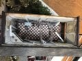
All of you, again, I really appreciate all of your knowledge and help! I think on this one I am going to try to keep it as simple as possible and just use the resistors. Most of the use will be fairly short on times to show people the lighted diorama, not prolonged on time, so if I can get the 5-10 hours out of a set of 4 C cells that will be sufficient as the batteries can be fairly easily replaced. My main concern, as I mentioned, is making sure the LEDs last a looong time as they are not easily replaced and for a buyer they might be very disappointed if they didn't last very long. These tiny SMD LEDs are wired through 1/8" polystyrene tubes into the interior of the buildings from below, some with heat bent angles (see photos) so most of the LEDs, except the signs, can be replaced with out tearing the models apart or even removing the display case, but they still are tricky to feed them in far enough so they just exit the tube end but not too far and when installed correctly they have plenty of air around them.
I have a bunch of 1k and 620 ohm resistors so I tried them out connected to a 3v 2x C cell pack and the 620 ohm still gives a fairly bright light, while the 1k ohm would be good for areas requiring less light like the street lights. I assume two the the 2 C cell packs in parallel for 3v would be the best way to go for longevity? (in the photo they are in series for 6v)
I have a bunch of 1k and 620 ohm resistors so I tried them out connected to a 3v 2x C cell pack and the 620 ohm still gives a fairly bright light, while the 1k ohm would be good for areas requiring less light like the street lights. I assume two the the 2 C cell packs in parallel for 3v would be the best way to go for longevity? (in the photo they are in series for 6v)
Attachments
-
 487.7 KB Views: 6
 -
 539 KB Views: 6
Last edited:
Ya’akov: I’m still considering your modules suggestions, it sounds really good; I guess I’m hesitating because I have no idea how it would all be hooked up and physically how it would attach to the plywood base which has about 1-1/4” clearance in height.Then it's just review!
But, it you catch back on, you can use it to choose resistors as needed. No doubt, resistors are the cheapest and simplest solution. I still think you could create your own modular arrangement using the boards I mentioned above. You can make standard configurations for power and charging, and not have to think too much when wiring and powering a diorama.
There are standard connectors, too. This will make things a lot easier. Let me know if you want information on the connectors and the tools needed to put them on.
These connectors are called pin headers or Dupont connectors and the standard 2.54mm (.1") pitch fits into the modules. Normally, you put the male pin headers on the modules and crimp the female connector parts onto the wires. They are cheap as dirt, ubiquitous, and (relatively) easy to terminate. The pin headers come in long strips designed to be snapped off to get the right number of pins for your use.
The female connectors come with shells of various sizes to accommodate different numbers of pins.
The are only a couple of downsides for your application. The headers with connectors in place can can be tall, but that can be mitigated using readily available right angle pin headers that will accept the female connectors parallel to the mounting surface.
The connectors are not polarized, so they could be plugged in backwards. This is a real possible problem when dealing with self-service. You could use a different type of connector with the same pitch, since 2.54mm is very standard, and this is probably the best solution. There are options with polarized, locking connectors which are very nice.
But there is a good chance the modules you buy will have the pin headers installed, and the Dupont connectors are much cheaper, and in several ways easier. What I do to reduce the risk is to color code the connector using paint markers. Choosing a bright color, I paint the edge and a bit of the front and back face of the female, then the corresponding proper side of the pin header similarly.
A warning in the documentation (which should be somehow included inside the model*) will tell the user to match the color code. This feels like 90% insurance.
*what I would do for the documentation is include a QR code that points at a PDF document. There are many advantages to this approach which I am pretty sure are fairly self-evident.
A suggestion: you say that some of the lighting would be very hard to replace. Since some LEDs will fail at some point there are a couple of things you can do to make life easier.
First, keep the drive current as low as you can manage. Heat is the number one enemy of LEDs, and the more current, the more heat. To do this don't make them run any brighter than you need to—it's worth spending some time tweaking the brightness to a minimum that works well.
You can also use more than one LED per position! If you need more brightness running two LEDs at lower current will keep each much cooler by spreading out the heat. Also, It possible, provide ventilation. If you can manage to make a way for air to circulate, the ambient temperature where the LEDs are mounted can be lowered and so their internal temperatures will follow.
You don't need active cooling but the more space you can give the LEDs, the cooler they will run. Think about how you could do this in a hidden way, internally.
Second, put more than one LED for each active LED and leave them unplugged (use those connectors!) and well labeled in an accessible part of the model where the deriver boards live. That way, if an LED fails, the user can simply plug in a new one—at least once—and no repair is required. LEDs can last for years if they are not driven hard, but like all electronic components that can experience "infant death".
This is when a component dies in the very early part of using it. This is generally a QC issue, since factory testing should catch such things, but your parts sources are not premium ones, and you could fall victim to sub-standard parts. It's even a good idea to mix batches of LEDs if you have such a thing. That is, combine LEDs from different orders and vendors to try to reduce the chance of being hit with a bad batch.
The same is true of the modules. All of these things are cheap, but if you can make them user serviceable, it can save you a lot of heartburn. Make them easy to replace by avoiding hot glue and the like and instead mounting them with a tab and a single screw.
View attachment 302269
something like this—of course a 3D printer is a really helpful thing
in this case, but you can use whatever is most convenient for you
The long tab portion remains fixed and the smaller tab can be captive
so to remove the module the screw is loosened and the tab rotated.
You can even use a couple of security head screws on the fixed tab
and a combination phillips/slotted head on the user removable part.
This is just a quick sketch, in practice you will want to accommodate
the connector(s) on the module and possible parts mounted on the
bottom, but this is easily done with relief and standoff.
(Also, investigate threaded brass inserts for making the screw
attachments solid and repeatably removable and replaceable.)
When I build things I like to put diagnostic indicators to simplify troubleshooting. That is, indicators of active power rails, outputs, and states to make it simple for someone to tell me what is wrong.
In your case, you'll want to know if the power is working, but you probably won't want to run them all the time. I think I would install an LED as a test instrument. Put one, with the standard connector, in the user accessible compartment and you can instruct the user to plug it into the suspect output. That would be the power supply (battery) output, the buck converter output, and each driver output. For completeness, I would probably include a male-male adapter to make testing the jumpers running from each module as well.
I know this sounds like a lot of work, and the initial design will take some thought and attention, but in the end cost-benefit seems to fall squarely on benefit side. It can potentially save you and your patrons a lot of time and frustration, and—though it is hidden—I consider it art as much as the visible work. The infrastructure of anything done right is very satisfying and I love to look at it and the art of the people that designed and built it.
For me that they would spend the time on the hidden bits enhances the whole thing and makes the attention to detail on the exposed parts even more satisfying and somehow complete.
I realize this is a lot of stuff that might seem to be outside your domain, and that's fair. Use all, part, or none of it as you calculate to be an improvement for your work. Your dioramas look great, and I would love the insides to look as great as the outsides making them true legacy pieces.
Best of luck whatever you do.
I’m also not familiar with these pin connectors and tool, but would like to know more. Most of my wires are 28-30 AWG and I solder connections and then use those shrink wrap tubes. The 0402 SMD LED lights have hairlike wires; my wire strippers can’t handle them as they are much smaller than 30 so I resort to using nail clippers and it’s really difficult. They are also difficult to solder onto resistors or extension wires and too thin for distribution blocks. Would these pin connections solve my problems or is there some other solution?
Thanks
Last edited:
| Thread starter | Similar threads | Forum | Replies | Date |
|---|---|---|---|---|
|
|
Lighting fixture | General Electronics Chat | 18 | |
|
|
Help need for airport diorama lighting | General Electronics Chat | 8 | |
| V | diorama welding arc | Automation, Robotics & Control | 9 | |
|
|
LED's to create a light effect for ocean diorama. | General Electronics Chat | 22 | |
| B | Solar Cell & LED diorama project... | General Electronics Chat | 24 |


