 Facebook
 Google
 GitHub
 Linkedin
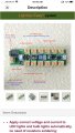
My miniature dioramas I build typically use 12-15 small SMD 3v LED lights. I’m currently using a power distribution unit that accepts 6-24v AC or DC in and has about 20 3v outputs and it’s rated at 1,000mA (example attached wit 12 outputs) I’m using it with 2x 9v alkaline batteries in Parallel for a 9v input to the board and they don’t seem to last very long. Would I be better off using 2x 2c cell battery holders in parallel for 3v output and a regular connector block for the 3v SMD lights all in parallel with the 3v supply so I’m not losing power to a power distribution board? Would this make a significant difference in run time? I have limited space under the diorama base and I want to just use battery power. Thanks for your help.
Attachments
-
 576.4 KB Views: 31
 -
 637.2 KB Views: 30


