You will see mostly DC with a well-defined amount of Ripple on top of it.
Rectified 3-Phase-Power has very little Ripple when compared to Rectified-Single-Phase-Power.
Rectified 3-Phase-Power never goes to "zero" like Rectified-Single-Phase-Power does.
.
.
.
In an automotive system there will be ripple voltage at the alternator output, but there will be mostly DC, just like LQC stated. The ripple will be less because of the battery biasing the output higher. An alternator by itself will have over a volt of ripple if there is no battery connected.
It depends on your meter.
Some meters, when set to AC, will tell you the ripple voltage.
A 6-pulse rectifier does have some ripple, although it is much smaller than the ripple of a single-phase bridge.
YES, you should be able to measure the ripple voltage, but the usefulness of the measurement varies with the meter scheme. SOME multimeters have an input terminal marked "OUTPUT", which uses a series capacitor to avoid DC affecting the reading when there is both AC and DC at the point to be investigated. So if your meter does not have a scheme to block the DC component of the voltage it is not likely that you will obtain a useful reading of the ripple voltage. That is the time to use an external series capacitor, often 0.1 microfarad, or up to 0.47 microfarads. The AC ripple voltage on an automotive 12 volt system will probably be less than 0.1 volt, if all the diodes are OK. It will be quite a bit higher if one diode has failed.
On an analog voltmeter that does not block DC on the AC range it will be difficult to know how much of the reading is the AC component. THAT is why I suggested using the "Output" connection, if one is available, OR an external coupling/DC blocking, capacitor.
YES, you should be able to measure the ripple voltage, but the usefulness of the measurement varies with the meter scheme. SOME multimeters have an input terminal marked "OUTPUT", which uses a series capacitor to avoid DC affecting the reading when there is both AC and DC at the point to be investigated. So if your meter does not have a scheme to block the DC component of the voltage it is not likely that you will obtain a useful reading of the ripple voltage. That is the time to use an external series capacitor, often 0.1 microfarad, or up to 0.47 microfarads. The AC ripple voltage on an automotive 12 volt system will probably be less than 0.1 volt, if all the diodes are OK. It will be quite a bit higher if one diode has failed.
This is leading me to believe that a diode is not 100% effective in blocking reverse current flow. I was thinking that the voltage downstream of the diodes was all DC. That the ripple was pulsating DC.
This is leading me to believe that a diode is not 100% effective in blocking reverse current flow. I was thinking that the voltage downstream of the diodes was all DC. That the ripple was pulsating DC.
That’s the wrong conclusion. The diodes completely block reverse current flow, but the ripple will still be present with no reverse current flow, simply because the input voltage is varying over time.
That’s the wrong conclusion. The diodes completely block reverse current flow, but the ripple will still be present with no reverse current flow, simply because the input voltage is varying over time.
Then the ripple must be only DC I suppose. Contrary to what is commonly stated. Thus the reason for my trying to get somewhat of a definitive answer to this subject.
The ripple is ON TOP of the DC. The diodes certainly block the reverse current, BUT if there is no battery and no filter capacitor, then the voltage will have a large ripple component. The ripple voltage is not a sine wave and so the formula to describe it is rather complex because it is represented by portions of two different sine waves. A graphic plot explains it very well.
Then the ripple must be only DC I suppose. Contrary to what is commonly stated. Thus the reason for my trying to get somewhat of a definitive answer to this subject.
.
It seems that You are simply missing parts of the "usual" "standard" equation.
If the Voltage never goes Negative, ( that is below zero ),
then it is absolutely DC, there is NO AC-Voltage, but probably a varying DC Voltage.
Which can also be stated as, DC-Voltage with "Ripple" on top of it.
If the Output of the Diodes is used to charge-up a large Capacitor,
then the Voltage on the Capacitor will rise to the highest peak-Voltage of the Ripple
which is on top of the (average) DC-Voltage.
But, of course, this assumes that there is NO LOAD that will Discharge the Capacitor.
If there is no Load to discharge the Capacitor,
it will remain charged to the highest peak DC+Ripple Voltage
and the Voltage will remain smooth and flat indefinitely,
( theoretically of course, as nothing in this World is "perfect" ).
When a Load to "zero-Volts", or "Ground" is then added, which would tend to discharge the Capacitor,
then the Ripple will start to get larger again.
How much Ripple depends on how large the Capacitor is, and how much Current the Load demands,
because the Capacitor will be supplying all of the Current needed
when the Voltage being supplied through the Diodes drops below the maximum peak DC+Ripple-Voltage.
And there You are,
You need to add a large Capacitor to your Schematic,
and with no external Load, You will then have "zero-Ripple-Voltage", only smooth DC.
As soon as You add a Load, the Ripple will return to some degree.
You can accurately calculate exactly how much Ripple will return with a Mathematical-Formula.
( But guesswork will quite often get You "close-enough" to provide satisfactory performance )
.
.
.
If the TS is able to visualize, or draw, three sine waves set 120 degrees apart, with the bottom edge set at zero. Then trace the topmost line as it passes from one sine wave to the next. THAT variation in height (amplitude) is the ripple voltage.
Adding a capacitor produces exactly the results posted in #12, which is a correct explanation but without my graphic description.
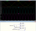
Below is the LTspice sim of the 3-phase Y circuit for 120Vrms per phase with a resistive load and no capacitor:
Note that the output voltage is the rectified (positive) sum of the three phases (minus a two-diode drop).
Below is the LTspice sim of the 3-phase Y circuit for 120Vrms per phase with a resistive load and no capacitor:
Note that the output voltage is the rectified (positive) sum of the three phases (minus a two-diode drop).
Really, the output voltage is at all times THE GREATER of the three voltages. as shown. So the ripple voltage seems to be a bit hard to guess accurately, but quite significant. About 48 volts of ripple
If the 3 Sine-Waves are pure-Sine-Waves,
and not being altered by things like Power-Factor-Anomalies, or subsequent odd Filter-Loadings,
the magnitude of the Ripple will be the product of a Geometric-Math-Formula,
and will always be a specific percentage of the Peak-Voltage.
But it seems that nothing in this World is ever perfect.
.
.
.
We are discussing automotive alternators and mostly they are not afflicted with a lot of power factor correction stuff. And especially since the diodes are right at the source of the power.
BUT what happens if we put a transformer primary in series with that output of the alternator, before any other device draws any current. Then that DC, with the voltage ripple on top, ,all flowing in one direction, generates a changing magnetic field in that transformer primary side, because with a constant load the current depends on the voltage. So then out of the secondary of that transformer will come some AC wave form. Probably ugly, but certainly AC, because DC does not work in transformers.
So my crazy deduction is that if we get AC out, probably we had AC in, even though we had 50 amps of rectified DC current passing through the primary. (This example assumes that the transformer core has enough iron to not reach magnetic saturation.)
Not sure where it goes from here..
Since the AC current pulses out of the 3-phase transformer are basically symmetrical plus and minus, the net DC current is zero, so the core will not saturate from the load current.
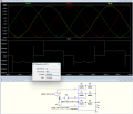
In the sim below, the RMS current from one phase is 226mA, but the average (DC component) is 26µA (likely not 0 due to calculation roundoff) error.
While the changing portion of the voltage is not so large, the DC portion, also flowing in the same primary wire is larger. THAT is the portion that might cause magnetic saturation.
You seem to not understand transformer operation.
There is no DC in the primary.
Even if there were DC in the secondary, which there isn't here, it would not translate to DC in the primary.

 Facebook
 Google
 GitHub
 Linkedin