Diode rectifier understanding.

Thread Starter

Smashmayo98

Joined Sep 12, 2018
11
Hi!

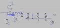
I'm currently studying EE (second semester) and just started analysing analog circuits and filters. In the circuits we're designing, there's a diode rectifier, but it is a bit different than a typical full-bridge and I can't seem to grasp the way it works!
Help is welcome and circuit will follow as an image. (EDIT: I made a little mistake on the circuit, the LM324 is powered by a +12V and a -12V, in the circuit it seems there's two -12V sources!)
 

Attachments

crutschow

Joined Mar 14, 2008
38,503
The TS's circuit has positive feedback.

Even if you changed the op amp to negative feedback, it's still a rather odd circuit.
The output would be the negative half cycle with a gain of two.
And it's not a true precision rectifier since D3 is not inside the feedback loop.
Also R4 likely needs to be connected to ground and the output taken from the junction of D3 and R4.
Not sure what R3, R5, and D4 are supposed to do. :confused:
 

Thread Starter

Smashmayo98

Joined Sep 12, 2018
11
The TS's circuit has positive feedback.

Even if you changed the op amp to negative feedback, it's still a rather odd circuit.
The output would be the negative half cycle with a gain of two.
And it's not a true precision rectifier since D3 is not inside the feedback loop.
Also R4 likely needs to be connected to ground and the output taken from the junction of D3 and R4.
Not sure what R3, R5, and D4 are supposed to do. :confused:

R4 is connected to another op-amp that has a gain equal to the voltage loss from the two diodes.
 

Thread Starter

Smashmayo98

Joined Sep 12, 2018
11
How are we supposed to answer your questions if you don't show the complete circuit?

Sounds like rather a kludge of a circuit.
Where did it come from?
I just wanted to understand the principle of the diode bridge. And it's from my Analog Electronics/Continuous time maths class !
 

crutschow

Joined Mar 14, 2008
38,503
I just wanted to understand the principle of the diode bridge. And it's from my Analog Electronics/Continuous time maths class !
Well, that's not a bridge, since two diodes are shorted together.

And whoever designed that circuit, does not now much about circuit design.
Or he's trying to throw you a curve-ball with a very odd circuit. :rolleyes:
 

Thread Starter

Smashmayo98

Joined Sep 12, 2018
11
Well, that's not a bridge, since two diodes are shorted together.

And whoever designed that circuit, does not now much about circuit design.
Or he's trying to throw you a curve-ball with a very odd circuit. :rolleyes:
Well it clearly works as a rectifier though. As seen from my oscilloscope and from Altium.
 

davidgreams

Joined Feb 2, 2019
3
No. A rectifier doesn't usually change voltage (except for a quirk of maths related to the way AC voltage is calculated, but that's beyond ELI5, and I'm sure it's not what you're talking about.)

A transformer changes voltage.

A power supply often contains a transformer (to change the voltage) and a rectifier (to convert the power to DC). They are two separate functions.

If that still doesn't make sense, then some more context might help. What type of devices are these rectifiers intended to be used with?
 
Top