k1ng 1337I'm at war with no one. However, I've noticed Bill seems to blast others when they
1) disagree with him
2) offer an alternative solution to their problem. Often Bill has been known to scold other users saying "That's not what the TS is asking for", and yet, I've seen him do the exact same thing.
3) Bill offers a solution that has been proposed. Others here have been known to say "I agree with so-and-so". But Bill offers advice like he's the one who came up with the idea, like he's the genius for doing so.
While I'm not at war with anyone, I do find some behaviors of some here to be annoying. Sometimes to an excessive degree. If I find it hard to hold my tongue usually I'll just unwatch a thread and go elsewhere, ignoring the one I find irritating.
I respect Bill's knowledge and skills. However, I feel somewhat less respected by him. That is an irritant to me. I've even seen others get disrespected; even go to war with him.
You've been here over a year. I'm approaching 2 years. It shouldn't take that long to figure out which users are abusive, which are obtrusive and which are out right belligerent. Maybe I'm being the later, but if I've offered a suggestion I've never seen anyone else offer the same advice. I've seen others say they disagree - which I highly respect - but only Bill has been the one I've observed who is either argumentative or just plain ignoring what others have posted. If get censured for this - that's a decision for the moderators. I'll take any punishment coming my way. I just wish there were a way to reign in those who blast others for not paying attention when they themselves pay little attention.
Hey Mister Bill - I respect you. I just don't care for someone taking credit where it is not due.
In the spirit of being stress free I suggest you don't take forums so seriously especially if they are geared towards helping the less educated because the internet is a place where ego is hard to correlate with actual credentials, in other words people can say anything with little repercussion. It is also the mark of a good debater to remain calm and collected otherwise your point is lost in the hostility. Bill has been helpful in my queries so naturally I would defend such a person. Anyway that's just my opinion and I don't mean to take topic away from TS.
The connection depends on whether you want to use it to indicate volts or current, or be selectable. The needles in those type of meters are always deflected by current.
And the switch, I could connect that in series to the input wires, so that it sits between the 220V power source and the transformer. That way when its switched off, the transformer will be off too. Is that correct, is that the best place to put the switch?
And what about the fuse? How do I connect that to the circuit?
I just saw this thread and certainly the 1N4007 is a poor choice for a 2 amp supply because it is a 1 amp diode. And likewise the capacitor certainly does need to have a higher voltage rating.
So it is quite clear that the kit sellers are either incompetent or dishonest, or both.
I'm not entirely sure how this circuit works yet, but it has a lot of resistors including a cement resistor. Could it be possible that it drops the amperage down to 1A before it reaches the 1N4007 diodes?
About the capacitor, I changed it to a 50V capacitor but the thing is, the circuit actually outputs 30V, not 42V so somewhere in the circuit, the voltage drops back to 30V.
The connections of the meter depend on if it reads volts or amps, (voltage or current). The switch and the fuse get connected in series with the mains connection to the transformer.
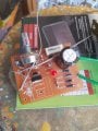
And while the soldering looks like most of the connections are OK, I see wires sticking up and bent over that can cause connections in places that should not be connected. But that may just be the way the light is shining.
The capacitor mentioned is in the circuit before the regulator portion and so it will indeed have the higher voltage at the no load condition. Linear regulators such as the LM317 require a supply voltage several volts above the regulated output voltage. So if you measure the voltage across that capacitor it will be several volts above that 30 volt output. I don't see a circuit for this system and so I don't know where that large resistor is in the circuit, but it is probably not in the input section before the regulator IC. .
From the value shown on the PC board photo and the location on the circuit board I am guessing that the large resistor is part of the over-current protection portion of the circuit, so it would not be reducing that capacitor voltage.
This is a view of the same side, the component side. The request was for a view of the solder side, so that we can understand how the components are connected and know what the circuit is. That will allow some folks to provide assistance if there are any issues, and also to se how the over-current protection portion of the supply works.
I'm not entirely sure how this circuit works yet, but it has a lot of resistors including a cement resistor. Could it be possible that it drops the amperage down to 1A before it reaches the 1N4007 diodes?
Resistors drop voltage, not current. Putting a resistor in front of the voltage regulator to drop voltage isn't very smart because the voltage drop will depend on the current through it. If you need to drop the voltage for the voltage regulator, you either put a zener diode or a pre-regulator in front of it.
Resistors drop voltage, not current. Putting a resistor in front of the voltage regulator to drop voltage isn't very smart because the voltage drop will depend on the current through it. If you need to drop the voltage for the voltage regulator, you either put a zener diode or a pre-regulator in front of it.
More important, putting a resistor in front of at least some of those regulators will create a very powerful oscillator up in the megahertz range. Been there, done that, and it took a few minutes to discover why I had a higher voltage on the output then on the input.
And thanks to "Mod" for reducing my confusion by merging the two threads.
Something that no-one has pointed out on this thread is the minimum breakdown voltage of the rectifier diodes. With a 30Vac sinewave fed into a bridge rectifier (ignoring any voltage drop), the peak output voltage will be root 2 times 30V = 42.4V. But the peak reverse voltage across the diodes will be double this value – this is something I was taught/told in college more than 40 years ago. Therefore allowing for voltage transients, the minimum diode breakdown voltage for a 30Vac input should be at least 100V.
Also there appears to be a lack of advice on the value of the capacitor to use.
A capacitor discharged into a resistive load, follows an exponential curve making the precise mathematics complex – but if you consider the capacitor loaded by a constant current then the calculation become very simple.
The ripple voltage (peak to peak) is given by the formula V = (I x t)/C
Where I is the current (A), t is the time between successive rectified voltage peaks (s), and C is the value of the capacitor (F).
Example:
Assume you want a ripple voltage of 2V (based on a mains frequency of 50Hz), with a current draw of 1A, we get;
2 = (1 x 0.01)/C
Transposing we get C = (1 x 0.01)/2 = 0.005F or 5,000µF
I certainly do not intend to be abusive at any time. But it does bug me a bit to have suggestions made that are not even close to addressing what the TS was asking about. AND, occasionally, when I can't sleep and start comments at 2:30 AM my time, I may even make a mistake. I am neither infallible nor invincible any more, nor have I been for quite a few years.
Well, @MisterBill2, I'd like to think we can get along. Largely because I'm in good company when you say you're not infallible. Neither am I. And sometimes we all have a bad day. Unfortunately we can take it out on others. So publicly, my apologies.
Also there appears to be a lack of advice on the value of the capacitor to use.
A capacitor discharged into a resistive load, follows an exponential curve making the precise mathematics complex – but if you consider the capacitor loaded by a constant current then the calculation become very simple.
The ripple voltage (peak to peak) is given by the formula V = (I x t)/C
Where I is the current (A), t is the time between successive rectified voltage peaks (s), and C is the value of the capacitor (F).
Example:
Assume you want a ripple voltage of 2V (based on a mains frequency of 50Hz), with a current draw of 1A, we get;
2 = (1 x 0.01)/C
Transposing we get C = (1 x 0.01)/2 = 0.005F or 5,000µF
Certainly Hymie is correct. And the math is also correct. BUt with a fast voltage regulator serving to keep the output constant, as long as the capacitor voltage does not fall below the output plus the minimum headroom value for that load current, the ripple will not be seen on the regulated output. I think that the TS mentioned, at some point, changing the capacitor to 2200MFD, almost half of the value calculated above.
The old "hip-shot" choice of 470 MFD is only off by a bit more than 10x, not too bad for no math involved at all. AND the TS value will be OK for lower voltages and lower currents.

 Facebook
 Google
 GitHub
 Linkedin