I saw worse soldering on a product in 1980 made by a new company in South Korea. It was called Goldstar and today is called LG which is "Lucky Goldstar". They are lucky that they learned how to solder with machines and get rich making flat screen TVs.
The usual ways. You can start where the circuit isn't functioning and work back until you find something that is, or you can start at the beginning and work your way forward until you find something that isn't working.
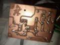
Your problem is the many leads that aren't soldered and, likely, bad solder joints.
Ah, so the issue is probably that not everything is soldered? So lets say I have some bad solder joints, can I fix them by melting the solder and letting it reset? Is there a possibility of permanently messing up the board by doing a bad job of soldering? An issue I been having is how difficult it is to get the component lead and board hot enough to melt the solder, I was worried the components might be damaged by the heat.
Probably the first issue is that the AC input leads are not soldered. Testing the board, it was reaching a maximum of 1.5V AC, but testing the leads directly it reaches 30V AC.
An issue I been having is how difficult it is to get the component lead and board hot enough to melt the solder, I was worried the components might be damaged by the heat.
What is the wattage, temperature, and shape of the iron/tip? If you lack soldering experience, large copper areas will be more problematic because they'll tend to sink heat away from where you want to solder.
As said, there are MANY points that are not soldered and a lot that are solder very badly.
Did you read the link in post #14 and did you have a look at the videos?
There isno reasson to attempt any diagnostics until all of the connections are correctly soldered. And all of the component leads at least positioned so that they do not contact anything else. The good news is that it does not look like anything was damaged by excess heat while using the soldering tool.
Did you by any chance use some lead-free solder? Such solder is inferior in every important aspect of soldering.
Rosin-core tin-lead solder and a temperature controlled soldering iron make an excellent solder joint in one second that is not long enough to damage an electronic part. Many noobies use a cheap dirty soldering iron that is too hot and it incinerates the important flux needed for cleaning the tip and solder joint.
I use one of those cheap soldering irons, and while it is an effort to keep the tip in good shape, it can be done. None of my small soldering irons cost as much as a replacement tip for most temperature controlled irons. The secret to making it work is in how it is done, mostly. Good flux is mandatory and good solder certainly is important as well. And just a bit of solder added toconduct heat from the tip to the parts being soldered is my secret. Soldering by some of the published instructions simply does not work. And there is no substitute for practice, and focus on the solder connection.
One more thing is that I do unplug the iron when I am not using it, that avoids a lot of tip degradation.
As long as the parts are clean so the solder can form an intermetallic bond.
Yes. Too much heat will lift pads/traces and burn the board laminate.
What is the wattage, temperature, and shape of the iron/tip? If you lack soldering experience, large copper areas will be more problematic because they'll tend to sink heat away from where you want to solder.
Its a cheap soldering iron, but Im getting better and better at using it. Watching those videos that Bertrus posted and practicing, Im starting to solder fast and effectively, Im going to solder everything and see how it goes
What wattage are you setting it to? Do you have any idea what the tip temperature is at the setting you're using? I use a Weller soldering iron (W-TCP 48W) and tip temperature is determined by the tip (600/700/800F).
The picture wasn't focused enough for me to determine whether the tip needed tinning. You want prevent oxidation from forming on the tip.
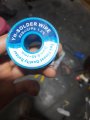
What does the 1.2% mean on your solder? Never saw that on any solder I've used.
EDIT:
If you have to do a lot of soldering, I think you'll find that a pencil type iron would be easier to use.
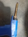
It looks like a soldering "gun" with a very dirty tip that has never been cleaned. Google shows that it is sold in India and Pakistan.
It has 3 power settings without any temperature control.
My solder is also 63/37 but is 2.5 times thicker and has almost double the 1.2% amount of rosin (2.2%).
Some solder flux is more active than others. Certainly the tip must be clean, but do not file it, use bit of flux and steel wool, they will work well. It is very challenging to solder with a tip that is not properly tinned, so that it has a solder coating. It might even be impossible to solder with that sort of tip. I would not even attempt it.
I just saw this thread and certainly the 1N4007 is a poor choice for a 2 amp supply because it is a 1 amp diode. And likewise the capacitor certainly does need to have a higher voltage rating.
So it is quite clear that the kit sellers are either incompetent or dishonest, or both.
Already said most of that. I missed the 1 amp diode point, but otherwise I've already said that the cap voltage should be significantly higher than supplied, and that it looks like the kit comes from someone who either doesn't know or worse, knows but doesn't care. a.k.a. dishonest. Those points have already been made. So thank you for agreeing with the rest of us.
Already said most of that. I missed the 1 amp diode point, but otherwise I've already said that the cap voltage should be significantly higher than supplied, and that it looks like the kit comes from someone who either doesn't know or worse, knows but doesn't care. a.k.a. dishonest. Those points have already been made. So thank you for agreeing with the rest of us.
Validation from 2 sources is better than 1 and is 3 better than 2. Not sure about you but I like when several users come to the same conclusions because it shows the logic is sound. Are you at war with MisterBill?
As for locating a problem in a piece of equipment, the best way is to understand how it should be working, and then to know how it IS working, at which time it should become clear where the problem is. Otherwise, start at the beginning and proceed toward the end, checking the conditions as you go. At some point the conditions will no longer be correct, that is usually where the fault is located. BUT BEWARE! If it is a system with feedback that may not work.
k1ng 1337I'm at war with no one. However, I've noticed Bill seems to blast others when they
1) disagree with him
2) offer an alternative solution to their problem. Often Bill has been known to scold other users saying "That's not what the TS is asking for", and yet, I've seen him do the exact same thing.
3) Bill offers a solution that has been proposed. Others here have been known to say "I agree with so-and-so". But Bill offers advice like he's the one who came up with the idea, like he's the genius for doing so.
While I'm not at war with anyone, I do find some behaviors of some here to be annoying. Sometimes to an excessive degree. If I find it hard to hold my tongue usually I'll just unwatch a thread and go elsewhere, ignoring the one I find irritating.
I respect Bill's knowledge and skills. However, I feel somewhat less respected by him. That is an irritant to me. I've even seen others get disrespected; even go to war with him.
You've been here over a year. I'm approaching 2 years. It shouldn't take that long to figure out which users are abusive, which are obtrusive and which are out right belligerent. Maybe I'm being the later, but if I've offered a suggestion I've never seen anyone else offer the same advice. I've seen others say they disagree - which I highly respect - but only Bill has been the one I've observed who is either argumentative or just plain ignoring what others have posted. If get censured for this - that's a decision for the moderators. I'll take any punishment coming my way. I just wish there were a way to reign in those who blast others for not paying attention when they themselves pay little attention.
Hey Mister Bill - I respect you. I just don't care for someone taking credit where it is not due.
I certainly do not intend to be abusive at any time. But it does bug me a bit to have suggestions made that are not even close to addressing what the TS was asking about. AND, occasionally, when I can't sleep and start comments at 2:30 AM my time, I may even make a mistake. I am neither infallible nor invincible any more, nor have I been for quite a few years.
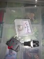
There are 3 more components that came with this kit but no instructions on how to hook them up. A switch, a fuse and a meter. How do I connect these components to the circuit?
The meter/guage, I should connect that in parallel to the output leads right? And the switch, I could connect that in series to the input wires, so that it sits between the 220V power source and the transformer. That way when its switched off, the transformer will be off too. Is that correct, is that the best place to put the switch?
And what about the fuse? How do I connect that to the circuit?

 Facebook
 Google
 GitHub
 Linkedin