 Facebook
 Google
 GitHub
 Linkedin
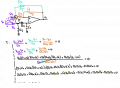
I recently found this paper online and would like to try to simulate the circuit in Figure 6, which (for convenience) I reproduce here:

Approaching opamps for the first few times, I present some doubts:
How do I know from such a circuit what the cutoff frequency is?
If I am not mistaken, I should first calculate the transfer function, right? And from that I can calculate the cutoff frequency .
In the past I calculated it for a Sallen-Key low-pass filter ... but in this circuit here I don't know how to calculate it (I attach the few calculations in the photo..).
Does anyone know how to calculate both?
EDIT: if I am not mistaken, the gain of this configuration is the gain of a differential amplifier, right? So in this case: -R2/R1+R5/(R5+R4)*(1+R2/R1).
I kindly ask for your confirmation.
Attachments
-
 329.1 KB Views: 1


