Developing super node intuition-what do you guys think?

Thread Starter

Electronics117

Joined Sep 9, 2017
27
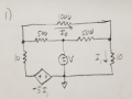
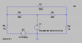
I have tried this problem 6 different ways, and i could have swore it was my sign conventions were messing me u (ass you can see there are convoluted things happening) but now that I think about it "maybe its a super node??" but isnt super mesh with KVL when you have 2 mesh currents going though a CURRENT source? or is it any problem at all, I'm going to go ahead and do nodal and a super node or mesh and super mesh if necessary because my answers are not matching my spice. Until then if someone wants to help me develop my intuition, thank you.
 

Attachments

Last edited:

The Electrician

Joined Oct 9, 2007
2,986
Why do some of the images show an inductor and a capacitor?

On the upper right hand part of the whiteboard I see this: I1 = 10 Ic. Yet the schematic plainly shows that I1 is the same current as Ic.
 

The Electrician

Joined Oct 9, 2007
2,986
I see that the image file named 20190301_192826 shows incorrect equations and an incorrect solution. I am able to get the same solution as shown on the board using those incorrect equations.

The image file named 20190301_201432 shows slightly changed equations. When I solve those equations, I don't get the same solution shown on the board. Furthermore, I don't think it's correct to take the voltage Vo to be -50 Ic; I think it should be -5 Ic. Your spice simulation took it as -5 i(R4) which is the same as -5 Ic.
 

Thread Starter

Electronics117

Joined Sep 9, 2017
27
To be honest I do not see supernode in this circuit https://forum.allaboutcircuits.com/attachments/capture-png.171272/
So, where is the prolem?
So were solving for i-not but in order to do so I was just solving I was just solving the mesh equations, but turns out my spice was wrong and Thr Electrician below was right I was trying to establish a relation of the dependent souces in terms that I can use in my mesh equations but it is already in terms that I can use.
Thank you a lot Jony, I poist questions on here every once in a while and its always helpful.
Thanks Jony
 

Thread Starter

Electronics117

Joined Sep 9, 2017
27
I see that the image file named 20190301_192826 shows incorrect equations and an incorrect solution. I am able to get the same solution as shown on the board using those incorrect equations.

The image file named 20190301_201432 shows slightly changed equations. When I solve those equations, I don't get the same solution shown on the board. Furthermore, I don't think it's correct to take the voltage Vo to be -50 Ic; I think it should be -5 Ic. Your spice simulation took it as -5 i(R4) which is the same as -5 Ic.
Thank you a lot man, I didnt even realize that. I am just so used to rewriting the dependent source.
That worked thank you!!
 

Thread Starter

Electronics117

Joined Sep 9, 2017
27
Why do some of the images show an inductor and a capacitor?

On the upper right hand part of the whiteboard I see this: I1 = 10 Ic. Yet the schematic plainly shows that I1 is the same current as Ic.
Sorry I attached too many problems i took them down, but thank you for disregarding those
 

Thread Starter

Electronics117

Joined Sep 9, 2017
27

Thread Starter

Electronics117

Joined Sep 9, 2017
27
I see that the image file named 20190301_192826 shows incorrect equations and an incorrect solution. I am able to get the same solution as shown on the board using those incorrect equations.

The image file named 20190301_201432 shows slightly changed equations. When I solve those equations, I don't get the same solution shown on the board. Furthermore, I don't think it's correct to take the voltage Vo to be -50 Ic; I think it should be -5 Ic. Your spice simulation took it as -5 i(R4) which is the same as -5 Ic.

hey man if you can help me think this through that would help too:

https://forum.allaboutcircuits.com/...cated-than-i-need-is-spice-failing-me.157359/

thanks
 
Top