
HI everyone, hope you are all well.
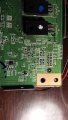
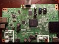
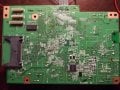
I’ve had a bit of an issue with my printer repair and I was hoping someone would be able to offer me some advice please. A leak in the printhead shorted the cable and blew a PCB SMD non-resettable fuse. The fuse is in series with the BJTs that presumably power the printhead. The printer works, firmware works, just doesn’t register cartridges and the CSIC is fine. So, I’ve moved the fuse off-board for easy access should I need to do this again and am using 20x5mm fuses. However, I do not know the value of the fuse. Epson are no help; they don’t know apparently. Is there any way I can determine the value at all? Or is it a case of trial and error going from low to high? The printer is old but a workhorse so would be nice to fix as I got a replacement printhead cheap. It’s an Epson Stylus SX515W which uses a CA48 Mainboard and the designation is F1, the only fuse present. I’ve attached some pictures. I’ve searched but cannot find a value for this. BJTs are unmarked so they don't help. The fuse measured approximately 1.56x0.75x0.45mm, LxWxD. Working back from this size seems to be up to 6 Amps which is way too much. I can’t imagine it being over 2 Amps. Can anyone over any advice as to how I should approach this problem? Any and all help would be appreciated. Thanks all in advance.
I’ve had a bit of an issue with my printer repair and I was hoping someone would be able to offer me some advice please. A leak in the printhead shorted the cable and blew a PCB SMD non-resettable fuse. The fuse is in series with the BJTs that presumably power the printhead. The printer works, firmware works, just doesn’t register cartridges and the CSIC is fine. So, I’ve moved the fuse off-board for easy access should I need to do this again and am using 20x5mm fuses. However, I do not know the value of the fuse. Epson are no help; they don’t know apparently. Is there any way I can determine the value at all? Or is it a case of trial and error going from low to high? The printer is old but a workhorse so would be nice to fix as I got a replacement printhead cheap. It’s an Epson Stylus SX515W which uses a CA48 Mainboard and the designation is F1, the only fuse present. I’ve attached some pictures. I’ve searched but cannot find a value for this. BJTs are unmarked so they don't help. The fuse measured approximately 1.56x0.75x0.45mm, LxWxD. Working back from this size seems to be up to 6 Amps which is way too much. I can’t imagine it being over 2 Amps. Can anyone over any advice as to how I should approach this problem? Any and all help would be appreciated. Thanks all in advance.
Attachments
-
 1.2 MB Views: 10
 -
 5.3 MB Views: 21
 -
 6.4 MB Views: 13
") I made the call and powered it up, firmware was fine, just prompted errors as expected and the voltage at the fuse rose to 42V. Seems like a lot but it is what it is. If it uses 16W when copying that would make current draw for the entire unit approx. 381mA @ 42V. Seems small but that is quite a lot of potential I suppose. This makes me think the fuse is a very small value. Possibly 630mA?
I made the call and powered it up, firmware was fine, just prompted errors as expected and the voltage at the fuse rose to 42V. Seems like a lot but it is what it is. If it uses 16W when copying that would make current draw for the entire unit approx. 381mA @ 42V. Seems small but that is quite a lot of potential I suppose. This makes me think the fuse is a very small value. Possibly 630mA?


