Facebook
 Google
 GitHub
 Linkedin
 Hi guys,
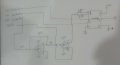
I am trying to design the EMG circuit using INA121P and OP07 Op-Amps.
I understand that EMG will need a preamplifier before any filtering is done, so i looked on the Internet and found preamplifier circuit in the data-sheet of the INA121P itself. (Schematic attached below)
I've built this circuit on a breadboard and now I want to check if it works.
In order to check it, I connected the +ve electrode of the EMG cable to O/P of my function generator giving out the positive pulse of 20Hz and 1.28V Amplitude and grounded both Ref and and -Ve electrode. (Is this approach right at all?)
However, the o/p of the preamplifier is not what desired, instead it is giving out a constant 7V O/P (Supply voltage for the INA and Op=Amps is +/-9V)
I know that I might be horribly wrong with this approach, but please bear with any mistakes I might have made and help me solve this problem!!
Thanks!!
*I didn't get OPA2131 in the local market that's why i went with OP07!
Last edited: