Designing PI controller anti-windup

Thread Starter

Pedro_Lopes_951

Joined Mar 24, 2020
9
Hello everyone,
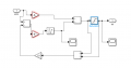
I am having some doubts about how to insert an anti-windup on my Microcontroller PIC dsPIC33EV. I designed a PI controller to control the charging of a batterie and I think all expect the Anti-wind up is correct. I will insert a screenshot of the C code I wrote of the Controler and the PI schematic I have done in Matlab so that if anyone knows how can I implement the PI on the microcontroller.3.PNG
 

Attachments

Last edited by a moderator:

trebla

Joined Jun 29, 2019
542
Why do you think if something is wrong with the code? How you use PI calculation output? Please insert your code between code tags (in edit window top menu Insert->Code) so people here will be able to see your code better.
 

Thread Starter

Pedro_Lopes_951

Joined Mar 24, 2020
9
C:
Kp=1;//Porpotional Gain
    Ki=0.1;//Integral Gain
    Kw=0.1;//anti-windup Gain
    Tsampling=100*10^-6;
    error_old=0;
    integral_old=0;
    integral_max=1;//
    integral_min=-1;//
    while(1){
        if(flagMain==1){
            IEC0bits.T1IE = 0;// Disable Timer1 interrupt
            Delay_us(10); // Wait for sampling time (10 us)
            AD1CON1bits.SAMP = 0; // Start the conversion
            while (!AD1CON1bits.DONE); // Wait for the conversion to complete
            AD1CON1bits.DONE=0;//Clear Convertion done status bit
            ADCValue = ADC1BUF0; // Read the ADC conversion result
            error_new=V_ref-ADCValue;
            integral_new=integral_old+Ki*(error_new+error_old)*Tsampling/2;// Area do trapezio
            if(integral_new>integral_max){//Anti wind up protect
                integral_new=integral_max;//
                }
            if((integral_new<integral_min)){
                integral_new=integral_min;
                }
            }
            PHASE2=  Kp*error_new+integral_new;//Ouput of the controller
            integral_old=integral_new;
            error_old=error_new;
 

Thread Starter

Pedro_Lopes_951

Joined Mar 24, 2020
9
Why do you think if something is wrong with the code? How you use PI calculation output? Please insert your code between code tags (in edit window top menu Insert->Code) so people here will be able to see your code better.
I just don't think the way I am doing the anti-windup is correct. The Phase2 variable is where the output of the controller.
C:
Kp=1;//Porpotional Gain
    Ki=0.1;//Integral Gain
    Kw=0.1;//anti-windup Gain
    Tsampling=100*10^-6;
    error_old=0;
    integral_old=0;
    integral_max=1;//
    integral_min=-1;//
    while(1){
        if(flagMain==1){
            IEC0bits.T1IE = 0;// Disable Timer1 interrupt
            Delay_us(10); // Wait for sampling time (10 us)
            AD1CON1bits.SAMP = 0; // Start the conversion
            while (!AD1CON1bits.DONE); // Wait for the conversion to complete
            AD1CON1bits.DONE=0;//Clear Convertion done status bit
            ADCValue = ADC1BUF0; // Read the ADC conversion result
            error_new=V_ref-ADCValue;
            integral_new=integral_old+Ki*(error_new+error_old)*Tsampling/2;// Area do trapezio
            if(integral_new>integral_max){//Anti wind up protect
                integral_new=integral_max;//
                }
            if((integral_new<integral_min)){
                integral_new=integral_min;
                }
            }
            PHASE2=  Kp*error_new+integral_new;//Ouput of the controller
            integral_old=integral_new;
            error_old=error_new;
 

trebla

Joined Jun 29, 2019
542
Are you tested how this code works? At first look i suggest add one windup countermeasure: if error is zero make integral_new also zero.
 

crutschow

Joined Mar 14, 2008
34,420
Integrator windup is one of the problems of emulating an analog linear feedback network designed for linear system elements.
You might consider digital Fuzzy Logic loop control, which doesn't use integrators and can also readily handle non-linear system elements.
 
Top