Designing dimmer circuit for LED ring lamp

panic mode

Joined Oct 10, 2011
5,439
Is that visible from the pictures of the boards I sent?
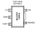
i see two inductors on those boards and fancy shape IC commonly found in LED drivers (PAM2861 or whatever)

1793214942149.png

one of the inductors is for step down (buck) converter.
the other is for that fancy shaped IC which generates constant current (boost) for LEDs.

i reverse-engineered one of beacons for vehicles (with bunch of flashing patternns). here they did not have first buck converter - here they used zener to regulate voltage for MCU.
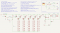
1793214835326.png
 

dl324

Joined Mar 30, 2015
18,502
Is that visible from the pictures of the boards I sent?
The specs on the heat shrink made me think it might be a constant current source.
Looking at the LED rings again I just noticed some writing I've previously missed. The temperature is the same for both. 3'000 K.
That would imply that one of the current sinks is more than 250mA. The color temperature has little to do with their brightness.
so a full cycle always has the same width, but the ratio between high and low changes?
Yes. Duty cycle refers to the time the output pulse is HIGH.
Ok. So could I use a standard 1k or 10k Ohm potentiometer for that? Or does it have to be something specific? How would I calculate what's needed?
In this case, either value will work because the load is the input of an opamp or comparator.
I currently have neither. So I'll take whatever's available near me.
If you think you'll be able to use them for other projects, I'd buy at least 10. I usually buy 100 to get more of a price break.
 

panic mode

Joined Oct 10, 2011
5,439
what would you hope to accomplish by varying frequency? with PWM frequency variations are usually seen as problem. in this case you are simply controlling light - as long as you cannot see flicker, you are fine. the key feature of using PWM (as opposed to changing voltage for example) is the efficiency. PWM controllers run cool without massive heatsinks.
 

MisterBill2

Joined Jan 23, 2018
28,525
IF the "on" portion of the PWM signal is a constant TIME PERIOD, then changing thefrequency will change the percent of the "ON TIME" by changing the length of the "OFF TIME" PERIOD. THAT DOES WORK.
Certainly it is a different way of looking at it, not as common as the standard method.
 

Thread Starter

yoxi

Joined Oct 14, 2026
9
@panic mode, @MaxHeadRoom, @dl324 and @MisterBill2
Thank you all for your continued input and all the helpful and interesting information!

In the meantime I've ordered the components needed to build the circuit @dl324 helped me work out.
If that fails for some reason, I'll have another look at what you suggested @panic mode.

I'll update you again once I've build everything to complete the thread.

---

About the frequency variation you all replied to:
I misunderstood how PWM controll works exactly and thought it worked by having the LEDs turn on more frequently. However I now understand that the frequency remains the same and only the ratio between on-time and off-time changes to increase or decrease brightness.
In that context I don't actually want the frequency to change, but the duty cycle.
 

panic mode

Joined Oct 10, 2011
5,439
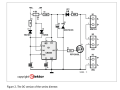
... the text says that R4 regulates the maximum supply voltage. ...
D3 is a zener and keeps supply voltage for LMC555 at 3.6V.
R4 is chosen based on supply voltage to absorb the difference between supply, and needs of D3 and LED1.
if dimmer is "off" (low duty cycle) then R4 voltage drop would be
VDC - Vf_led1 - Vd3.

Vf_led1 is about 2.3V
Vd3 is 3.6V

so if VDC is 13.8V, R4 would need to absorb:

13.8 - 2.3-3.6 = 7.9V.

to handle that R4 power need to be greater than P=U^2/R
so in this case P of just 0.11W would be burned off as heat and R4 can be 1/4W specimen.
but if VDC is 24V, then dissipated heat is massive 0.58W so 1W resistor would be required.

btw. this is a bit tricky circuit.... R4 does not supply current to charge C2 continuously, it only does so when T1 is off.
but since in PWM duty is variable, so is the off time and that means that time when T1 is off. in other words, T1 cannot be 100%.
while this is still rather neat, low loss, low part count solution, i am not quite big fan of it for that same reason (close but not full 0-100% range)
and the fact that P1 is not GND referenced limits versatility of the circuit. sure it can be controlled by P1, but not by an analog input.

1793632583753.png
 
Last edited:

dl324

Joined Mar 30, 2015
18,502
90 LEDs on the large ring
20 LEDs on the small ring
The brightness of the individual LEDs seems to be the same when at max current.
In the meantime I've ordered the components needed to build the circuit @@dl324 helped me work out.
If that fails for some reason, I'll have another look at what you suggested @@panic mode.
Make sure you test (under current limited conditions) the LED strings to make sure they'll tolerate 24V. With 90 and 20 LEDs, they must use a series+parallel configuration.
 

panic mode

Joined Oct 10, 2011
5,439
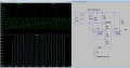
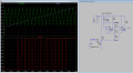
just for sake of completeness, here is one example of PWM circuit where duty can be controlled by voltage (and go full 0-100%):
1793638041577.png

to translate narrow control voltage range (previously 0.6-1.8V) to something more practical, like 0-5V, one just need couple of resistors (R8,R9,R10)
1793639300605.png
 
Last edited:

MaxHeadRoom

Joined Jul 18, 2013
30,881
However I now understand that the frequency remains the same and only the ratio between on-time and off-time changes to increase or decrease brightness.
In that context I don't actually want the frequency to change, but the duty cycle.
This has always been the reason I use this method, e.g. as typically shown in the Lava lamp mod I implemented.
 
Top