Designing dimmer circuit for LED ring lamp

Thread Starter

yoxi

Joined Oct 14, 2026
9
Dear All


I've recently disassembled an LED lamp because the touch-buttons for it stopped working. I now intend to replace the electronics inside with physical controls, more specifically a potentiometer (with an end-switch if possible). This would allow me to set a dimming level permanently by leaving the potentiometer at a certain level and I could turn the lamp on and off via the switched power-socket (instead of having to press the annoying touch-button every time it gets power).

The lamp is made up of two seperate LED array rings: a larger one pointing to the ceiling and a smaller one intended for reading.

I now require some help designing a circuit to dimm the LED rings.


Here's what I'm working with:

Electronics:
The pre-existing electronics showed a maximum current rating for both lamps. Using this I tested for a maximum voltage until that current is used. I’ve also tested the minimum required voltage to have the LEDs visibly turn on.

Power supply (existing)24 VDC1.5 A
LED ring (large)14 - 19.3 V0.9 A
LED ring (small)12 - 16 V0.25 A

Space requirements:
The housing is an oval cylinder with two 12 mm rods running through it. The front has two 16 mm holes that used to house the touch-buttons and where I now want to mount the potentiometers. Enlarging the holes is possible if necessary.

Additionally, I’d like to keep costs as low as possible, say below 50 bucks.
Housing measurements (drawing not accurate)

What I’ve attempted so far:

I’ve tried designing a control-circuit as seen in the picture below, trying to regulate the current flowing through the LED by using a BJT transistor controlled through a potentiometer.
Circuit diagram
The circuit is then doubbled to controll both LEDs. Given the different voltage requirements, the compontents would need to be different for each LED ring.

I’ve attempted to calculate the needed components for this layout, however I find myself out of depth when it comes to variable circuits and components working with a voltage range.

For example: I’ve found a transistor (TIP47, see data sheet, (for the larger LED ring)) which can handle the current needed and through that calculated the value of the resistor. This component has a 1V voltage drop from Collector to Emmiter. The current is 0.9 A and the current coming from the base is negligable. Meaning the voltage over the resistor is between 3.7 and 9V, leading to a resistance of 4.1 - 10 Ohms.

This is where my knowledge ends however. I don’t know how to decide on what resistor to finally use and how it affects the circuit when the LED is dimmed. Additionally, I don’t know how to figure out the resistance range of the potentiometer and wether I’ve chosen the transistor correctly.

I now ask for your support here.
Is this circuit itself even correct?
Does it do what I expect of it?
Is there potentially a better or easier way of achieving my goal?
What components with what exact values do I need to complete this circuit?

Kind regards and many thanks in advance
yoxi
 

Attachments

dl324

Joined Mar 30, 2015
18,502
Welcome to AAC!
Is this circuit itself even correct?
Power dissipation will be an issue. Something will have to dissipate about 5W for the large ring when it's at full brightness.
Is there potentially a better or easier way of achieving my goal?
I think it would be better to use a PWM and use a MOSFET that can handle more than 24V on the gate for switching.

Here's something I posted in another thread.
1791985972115.png
IIRC, the duty cycle range was around 20-80%. It would require different, and more, parts to get 0-100%.
 
Last edited:

MisterBill2

Joined Jan 23, 2018
28,525
IF the TS is able to select the supply voltage to provide the maximum light when the series resistance is close to zero, then the heating will be less. BUT CERTAINLY using PWM at a frequency that will not cause flickering will be a better method of dimming.
PWM dimmers might be found in the "Schematics For Free" website.
 
Last edited:

Thread Starter

yoxi

Joined Oct 14, 2026
9
PWM dimmers might be found in the "Schematics For Free" website.
Thx for your reply.
Based on your recommendation I've found a promising circuit (see attachments).
However I don't quite understand the principle of PWM controls...
If I use the suggested circuit, I asume that i still need to drop down the voltage from the 24V source to the maximum each ring can handle, right? So 19.3V for the large one and 16V for the small one.

How would I do that? Because to my understanding, the current flow isn't consistent because of the PWM controls.

And would I need to change R4 due to my difference in supply voltage?

Furthermore the text says that R4 regulates the maximum supply voltage. I asume thats for the left part of the circuit with the IC. Though the IC datasheet say it requires a maximum supply voltage of 15V.
Am I misunderstanding something here?
 

Attachments

MisterBill2

Joined Jan 23, 2018
28,525
Certainly the allowable maximum voltage is a real limitation that must be considered. Have you investigated the original controls package to see what it contains, as far as the actual circuit??
Have you considered any possible repair efforts for the original control module?? If the original buttons were actual switches, then replacing them would be my first choice effort.
 

Thread Starter

yoxi

Joined Oct 14, 2026
9
Have you considered any possible repair efforts for the original control module??
The original circuitry burned when an electrician came to do repairs on our mainboard and accidentally touched the wrong wires together. So i couldnt recognize anything on the old circuitboard due to the burnmarks and the heatshrink that surrounded the whole board cooked and melted around it.

If the original buttons were actual switches, then ...
They were touch-buttons with a metal centre and a metallic paintjob on the outside. Your finger made the connection. These were used to turn the lamps on and off aswell as dimming, by pressing and holding them while the lamp is turned on.
Due to the metallic paint peeling off over the years, it worked terribly regardless, so I planned to replace them anyways. The electrical incident just gave me a reason to finally do it.

Certainly the allowable maximum voltage is a real limitation that must be considered.
While I appreciate you taking the time to respond, in all honesty, these vague responses in relation to my questions really isn't helping me understand the matter at hand better. Which is why I'd kindly like to ask you to be more specific if you can. I'd really like to make this repair as well as gain some knowledge about circuit design. While I've worked with electronics on the application side, as well as having a lot of soldering experience, my knowledge on actually designing circuits is very limited (apart from basic physics calculations).
 

MisterBill2

Joined Jan 23, 2018
28,525
This thread as become very confusing indeed!!
AND, the circuit shown in post #2 does not include any output connection from the oscillating part of the circuit..

A variable PWM voltage can be fed thru a filter to produce a variable DC voltage. THAT is a fairly common scheme.
 

Thread Starter

yoxi

Joined Oct 14, 2026
9
A variable PWM voltage can be fed thru a filter to produce a variable DC voltage. THAT is a fairly common scheme.
And how would I go about doing that?
Do you have an example? A schematic?
Possibly even showing how its done in my case here with specific parts / numbers?
 

dl324

Joined Mar 30, 2015
18,502
Do you have an example? A schematic?
Since you have not saw fit to respond to my post, I should just let you spin your wheels.
However I don't quite understand the principle of PWM controls...
PWM (Pulse Width Modulation) is a preferred technique for varying the brightness of LEDs. Instead of depending on the non-linear optical response of LEDs, PWM turns them on and off at a varying duty cycle to change perceived brightness.

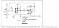
If you require full on to full off variation, you can use this circuit:
1792336038584.png
It uses opamps as comparators for U1B and U1C, but that's okay because switching speed isn't important and the outputs (and inputs) are rail-to-rail. A downside is that the operating voltage is only 2.7-6V. That would require you to use a voltage regulator to reduce the voltage from your 24V power source to 6V. Doing that would require you to use a logic level N channel MOSFET to switch the low side of the LEDs with something like IRLZ44N. I'd use an AO3400 which is a now obsolete surface mount device. It can handle around 5A and cost around $0.02 and is less overkill.

If 20-80% brightness is okay, you can build two of the circuits in post #2 with a single 8-pin DIP. I mentioned in that post that you needed to use a MOSFET that allowed a 24V gate voltage. If you use a voltage regulator to reduce the voltage to under 20V, you could use an IRFZ44N to switch the low side of the LEDs. Under 12V if you used AO3400.
 

Attachments

MisterBill2

Joined Jan 23, 2018
28,525
What I have not seen is any mention of the actual mains voltage supply, or if any paortion of the original lamp system power supply is available.
Control of LED lighting is usually a challenge because LEDs are very non-linear, like most diodes. Pulse WIDTH Modulation (PWM) is a useful scheme for controlling average power, but how it would work with LED lighting is a question,since LED response to input power is close to INSTANT, very different from incandescent lights.

So the PWM full voltage control scheme results MIGHT NOT BE SATISFACTORY!!

Possubly others have already expperienced PWM control of LED lighting and can provide actual results for us all.
 

MaxHeadRoom

Joined Jul 18, 2013
30,881
I did a project for a poster here that needed a lava lamp modified, it had three strings of series connected LED's, each string consisted of a different colour, he required that each string constantly ramp up and down in turn over about 6 sec for each ramp up and down time.
I used a small 8 pin picmicro with PWM outputs for each string.
It worked very successfully , with very smooth ramp up and down. !
 

Thread Starter

yoxi

Joined Oct 14, 2026
9
@dl324
Since you have not saw fit to respond to my post, I should just let you spin your wheels.
In all honesty, I never scrolled back to the top and never saw your first post, my apologies.
I appreciate you responding once again, especially with this level of detail!

PWM (Pulse Width Modulation) is a preferred technique for varying the brightness of LEDs. Instead of depending on the non-linear optical response of LEDs, PWM turns them on and off at a varying duty cycle to change perceived brightness.
So the LEDs just spend less time turned on, giving us the appearence of being dimmed as our eyes can't percieve the flickering?

If you require full on to full off variation, you can use this circuit:
View attachment 372366
I asume the four Vcc terminals are the 2.7-6V ones you mentioned? And Vin would be a source for the LEDs rated voltage (i.e. 19.3 for the large ring and 16 for the small one)?

In your experience: is 0-100 brightness even neccessary? Or do you think 20-80 is sufficient for a main living room floor-lamp pointed at the ceiling? (I'm asking because I'm wondering if one of the circuits is significantly more expensive and thus even worth building.)

Furthermore: Is it safe to have a circuit under pemanent power, but have the PWM cycle set to 0, so the lamp is off? Or would it be better to use a potentiometer with a built-in switch at the end? (Or an additional seperate switch of course)

Additionally I don't quite understand the two outputs of the circuit. The triangular wave is fed into U1C to create the PWM signal, right? So is the triangular wave output itself needed aswell or just for the purpose of the PWM output?

That would require you to use a voltage regulator to reduce the voltage from your 24V power source to 6V.
Based on the differences in required voltage of the LEDs and basically any circuit I build... don't I need a voltage retulator regardless? Neither LED can handle 24V, so i asume they'd be destroyed. Or does their behaviour change when powered through a PWM signal?

@MisterBill2
What I have not seen is any mention of the actual mains voltage supply, or if any paortion of the original lamp system power supply is available.
Mains here is 230V at 50Hz and im using the pre-existing power-supply that transforms that to 24V with a maximum current of 1.5A. This is the lamps original power supply. However, any other electronics burned / melted and were hence thrown away. So I'm working with the numbers from the table given in the original post:
Power supply (existing)24 VDC1.5 A
LED ring (large)14 - 19.3 V0.9 A
LED ring (small)12 - 16 V0.25 A

@MaxHeadRoom
I did a project for a poster here that needed a lava lamp modified, it had three strings of series connected LED's [...].
It worked very successfully , with very smooth ramp up and down. !
Thank you for sharing. I asume there was no requirement for them to turn off completely?
 

dl324

Joined Mar 30, 2015
18,502
In all honesty, I never scrolled back to the top and never saw your first post, my apologies.
I find that a little difficult to believe. My response was the first one.
So the LEDs just spend less time turned on, giving us the appearence of being dimmed as our eyes can't percieve the flickering?
The PWM frequency determines whether flickering would be noticeable. Since the human eye can't perceive flickering from line powered lights (50Hz in your case), a PWM frequency of 800Hz in my first example wouldn't give noticeable flickering.

LEDs respond much faster than incandescent lights, so the PWM frequency can be higher than 1200Hz.
I asume the four Vcc terminals are the 2.7-6V ones you mentioned? And Vin would be a source for the LEDs rated voltage (i.e. 19.3 for the large ring and 16 for the small one)?
Yes, the 4 VCC terminals are the same nodes/potential. VIN would be from 0-6V (the maximum supply voltage) because the inputs are rail-to-rail (meaning input voltages must be between the supply voltages). Actually the MAX094 allows the input voltages to be slightly above and below the supply voltages.

I don't like how they showed power on the opamps. All of the opamps are in the same package, so showing power connections to one opamp would have been sufficient. The schematic editor I use doesn't usually show power connections for opamps and I actually prefer that style.
In your experience: is 0-100 brightness even neccessary? Or do you think 20-80 is sufficient for a main living room floor-lamp pointed at the ceiling? (I'm asking because I'm wondering if one of the circuits is significantly more expensive and thus even worth building.)
It depends on what you want. If you want full on and full off capability, the single comparator PWM wouldn't be sufficient.
Furthermore: Is it safe to have a circuit under pemanent power, but have the PWM cycle set to 0, so the lamp is off? Or would it be better to use a potentiometer with a built-in switch at the end? (Or an additional seperate switch of course)
If you wanted both lamps to be off, I'd just turn off the power switch. But, operating the PWM at a duty cycle of 0 wouldn't be a significant problem. It will waste a small amount of power in the 0 duty cycle case.
Additionally I don't quite understand the two outputs of the circuit. The triangular wave is fed into U1C to create the PWM signal, right? So is the triangular wave output itself needed aswell or just for the purpose of the PWM output?
The triangle wave is what is used to generate the PWM pulses.
Based on the differences in required voltage of the LEDs and basically any circuit I build... don't I need a voltage retulator regardless? Neither LED can handle 24V, so i asume they'd be destroyed. Or does their behaviour change when powered through a PWM signal?
The original circuit I posted can operate from 24V. The 3 opamp version uses a low voltage opamp, so you'd need a 6V voltage regulator. You could also use a voltage regulator for the single comparator circuit. That would allow you to use a more common MOSFET (many have maximum gate voltages of 20V).

This assumes that you can switch the LEDs low side. Switching high side introduces some complications.
 

MaxHeadRoom

Joined Jul 18, 2013
30,881
Thank you for sharing. I asume there was no requirement for them to turn off completely?
One string ramping up or down, one other full on, the third was off.
IOW Each string was under PWM control in turn .
Just 8 pin micro and a mosfet for each bank.
 

Thread Starter

yoxi

Joined Oct 14, 2026
9
@MaxHeadRoom
A very compact solution then, thanks for the detail.

@dl324
I find that a little difficult to believe. My response was the first one.
While I can see that, I can't change your opinion on it. So I suggest we move on, as I've already apologized.

The PWM frequency determines whether flickering would be noticeable. Since the human eye can't perceive flickering from line powered lights (50Hz in your case), a PWM frequency of 800Hz in my first example wouldn't give noticeable flickering.

LEDs respond much faster than incandescent lights, so the PWM frequency can be higher than 1200Hz.
Gotcha, so theres no issue with flickering, regardless of the dimming level. I see your original circuit has a range of 800-1200 Hz, so the entire range would be way out of the human perception.

Yes, the 4 VCC terminals are the same nodes/potential. VIN would be from 0-6V (the maximum supply voltage) because the inputs are rail-to-rail (meaning input voltages must be between the supply voltages). Actually the MAX094 allows the input voltages to be slightly above and below the supply voltages.
So the entire circuit could be powered by 6V through a voltage regulator?
And the PWM output from that would switch a MOSFET on the low side (as in after?) of the LED ring?

This would mean that I need three voltage regulators. One for 6V to power the circuit, one for 19.3V for the large ring power input and one for 16V for the small rings power input?

It depends on what you want. If you want full on and full off capability, the single comparator PWM wouldn't be sufficient.
If you wanted both lamps to be off, I'd just turn off the power switch. But, operating the PWM at a duty cycle of 0 wouldn't be a significant problem. It will waste a small amount of power in the 0 duty cycle case.
Ok, both circuits would work, so it's just up to my personal preference then.

The original circuit I posted can operate from 24V. The 3 opamp version uses a low voltage opamp, so you'd need a 6V voltage regulator. You could also use a voltage regulator for the single comparator circuit. That would allow you to use a more common MOSFET (many have maximum gate voltages of 20V).

This assumes that you can switch the LEDs low side. Switching high side introduces some complications.
Basically both options are very similar, the original circuit would just require one less voltage regulator (unless I decide to lower it to 20V).

Based on what I've learned so far I prefer the 0-100% circuit.

---

I'm still missing some things though:

How do I control the frequency of the PWM signal? I don't see any potentiometers in the circuit drawing and the pdf you send says that you can controll the frequency through R1 and R2. It says the relationship between them controls the frequency aswell as the amplitude of the output. Is that a problem (the amplitude changing aswell)?

Is there a simple way of making your own votlage regulator with the specific 19.3, 16 and 6V outputs I need?
I did find one that drops the voltage from 24 to 3.3, which I asume would also work in the 0-100 circuit (2.7-6V range)?
However I can't find any that drop the votlage to either 19.3 or 16V with the local suppliers here.

I'd build two of these circuits, one for each ring, connecting them in parallel under the 24V supply and regulating each side down to what is needed.
I could then still add a switch each just before the voltage regulators to toggle each circuit and thus lamp on and off. Is that correct?

Could you also tell me your schematic editors name, so I could draw up the whole circuit as an overview?
 

dl324

Joined Mar 30, 2015
18,502
So the entire circuit could be powered by 6V through a voltage regulator?
The PWM circuit would be 6V. The LEDs would be connected to the 24V supply.

I'm not sure what you were trying to tell us when you posted information about measuring the voltage on the LEDs. Dimming circuits wouldn't typically change the voltage across the LEDs; they'd use PWM.
the PWM output from that would switch a MOSFET on the low side (as in after?) of the LED ring?
Switching low side means connecting/disconnecting ground. High side switching would mean connecting/disconnecting power (24V).
This would mean that I need three voltage regulators. One for 6V to power the circuit, one for 19.3V for the large ring power input and one for 16V for the small rings power input?
I doubt that there were separate voltages (regulators) for each of the LED rings. That wouldn't make sense.

It would make more sense for both LED rings to be driven from the same 24V supply.
How do I control the frequency of the PWM signal? I don't see any potentiometers in the circuit drawing and the pdf you send says that you can controll the frequency through R1 and R2. It says the relationship between them controls the frequency aswell as the amplitude of the output. Is that a problem (the amplitude changing aswell)?
The PWM frequency isn't variable. It's set by the R and C of the integrator and the voltage divider consisting of R1 and R2.

If by output, you mean the PWM signal, it's fixed by the supply voltages because the output of U1C swings rail-to-rail.
Is there a simple way of making your own votlage regulator with the specific 19.3, 16 and 6V outputs I need?
I did find one that drops the voltage from 24 to 3.3, which I asume would also work in the 0-100 circuit (2.7-6V range)?
However I can't find any that drop the votlage to either 19.3 or 16V with the local suppliers here.
I don't think you need 3 different voltages. Just the 24V that powered the lamp and a 6V regulator. For the 6V regulator, I'd use LM317 or LM317L. The former being good for 1.5A and the latter 100mA. You set the output voltage with 2 resistors.
Could you also tell me your schematic editors name, so I could draw up the whole circuit as an overview?
I use an old, freeware version of Eagle (4.13r1) that some here claim is too difficult to learn. I've used several other schematic editors and didn't think any of them were particularly difficult to learn. I settled on Eagle due to its capabilities and stopped looking.

The newer versions of Eagle require a subscription and they don't offer me anything I really need.
 

Attachments

Thread Starter

yoxi

Joined Oct 14, 2026
9
The PWM circuit would be 6V. The LEDs would be connected to the 24V supply.
Ye, sorry. The PWM circuit is what I meant.

I'm not sure what you were trying to tell us when you posted information about measuring the voltage on the LEDs. Dimming circuits wouldn't typically change the voltage across the LEDs; they'd use PWM.
You asume that both LED rings were previously driven by 24V through a PWM circuit aswell?

The reason I posted about that:
On the burnt circuits where the pin for the LEDs were connected I could make out 2 things: a maximum wattage and amperage each. 18W and 0.9A for the large one and 4W and 0.25A for the small one. Through that I calculated the voltage.
Then, just to be sure I tested it with a variable power supply, starting low and increasing the voltage until the amperage hit the 0.9 or 0.25. The voltages I got from the test were 19.3 (instead of 20) and 16 as expected.
I thought this information would be useful in designing a new circuit. However with the PWM drivesystem I don't know how these limits behave or change. (For example I've read that LEDs produce way less heat with a PWM drive compared to straight DC power because they're only turned on for a short time.)

Is there a way of finding out testing wether the LEDs can actually be directly supplied with 24V?

Switching low side means connecting/disconnecting ground. High side switching would mean connecting/disconnecting power (24V).
Gotcha, hence why high side switching is more difficult.

I doubt that there were separate voltages (regulators) for each of the LED rings. That wouldn't make sense.

It would make more sense for both LED rings to be driven from the same 24V supply.
That would make more sense indeed.
I remembered a friend had the same lamp and asked him if he could disassemble his to look at the circuitboards since mine are gone and he sent me the attached pdf with the pictures. Maybe those help figure things out.

The PWM frequency isn't variable. It's set by the R and C of the integrator and the voltage divider consisting of R1 and R2.

If by output, you mean the PWM signal, it's fixed by the supply voltages because the output of U1C swings rail-to-rail.
I may be confused at how the PWM system works again then. Doesn't the PWM frequency, so the pulse width, determine how long the lamp stays turned on?
I'd need to control that through a potentiometer in order to control the lamps dimming level, right? And I don't see where that comes into play in the circuit so far.

I don't think you need 3 different voltages. Just the 24V that powered the lamp and a 6V regulator. For the 6V regulator, I'd use LM317 or LM317L. The former being good for 1.5A and the latter 100mA. You set the output voltage with 2 resistors.
Would the 1.5A version be overkill? Since it doesn't actually need to power the whole lamp, but just the circuit? Or is it more of a "safety-first" thing of choosing the higher current rated one to be on the safe side?

I use an old, freeware version of Eagle (4.13r1) that some here claim is too difficult to learn. I've used several other schematic editors and didn't think any of them were particularly difficult to learn. I settled on Eagle due to its capabilities and stopped looking.

The newer versions of Eagle require a subscription and they don't offer me anything I really need.
I'll look into that, thanks.

---

Conslusion so far:
The main thing left to do is to figure out if I can supply the LED rings with 24V.
We'd also have to find a way of controlling the dimming levle using a potentiometer.

Other than that I think you've been a massive help in working out a good solution and I think we covered everything necessary.
Or can you think of anything we're missing?
 

Attachments

dl324

Joined Mar 30, 2015
18,502
I remembered a friend had the same lamp and asked him if he could disassemble his to look at the circuitboards since mine are gone and he sent me the attached pdf with the pictures. Maybe those help figure things out.
The two boards are the same.
Is there a way of finding out testing wether the LEDs can actually be directly supplied with 24V?
They may have been driven by current sources. That's another preferred method of driving LEDs.

What is different about the small and large rings? Does the larger have more LEDs? Are the LEDs in the small ring dimmer?

LEDs come in many brightness categories. The smaller ring might have used LEDs with less light output at a given current.

Can you access the terminals on individual LEDs?
I may be confused at how the PWM system works again then. Doesn't the PWM frequency, so the pulse width, determine how long the lamp stays turned on?
The frequency typically stays the same (it changes with duty cycle in the single comparator circuit). Brightness is controlled by the duty cycle (amount of time the pulse is HIGH).
I'd need to control that through a potentiometer in order to control the lamps dimming level, right? And I don't see where that comes into play in the circuit so far.
The potentiometer in the first circuit I posted determines duty cycle. In the 3 opamp circuit, VIN is variable (e.g. from a potentiometer).
Would the 1.5A version be overkill? Since it doesn't actually need to power the whole lamp, but just the circuit? Or is it more of a "safety-first" thing of choosing the higher current rated one to be on the safe side?
It depends on what you have. I have hundreds of LM317 on hand. I have around 100 of LM317L.

At jameco.com, the difference in price is $0.39 vs $0.25, for quantity 10. But they have LM317L on clearance.
1792680279993.png
1792680304506.png
 

Thread Starter

yoxi

Joined Oct 14, 2026
9
Apologies for the late response. Been on a short getaway.

The two boards are the same.
So safe to asume they've both been driven by the full 24V?

They may have been driven by current sources. That's another preferred method of driving LEDs.
Is that visible from the pictures of the boards I sent?

What is different about the small and large rings? Does the larger have more LEDs? Are the LEDs in the small ring dimmer?
90 LEDs on the large ring
20 LEDs on the small ring
The brightness of the individual LEDs seems to be the same when at max current.

Looking at the LED rings again I just noticed some writing I've previously missed. The temperature is the same for both. 3'000 K.
Large RingSmall Ring
Power18WEGLO
Voltage19.2V16V
Current900 mA constant current240 mA constant current
LED Temperature3'000K3'000K
LedType?-Diameter?-LedCount-Power-Temperature2835-D229-90-18W-3000K2835-D99-20-4W-3000K
ManufacturerEGLOEGLO

D229 and D99 might refer to the rings outer diameters, as they are 229mm and 99mm respectively.
2835 is aparently an led type, so they're the same for both rings.
(I've attached a picture of the rings)

Can you access the terminals on individual LEDs?
I might barely be able to make a connection with the multimeter, yes.

The frequency typically stays the same (it changes with duty cycle in the single comparator circuit). Brightness is controlled by the duty cycle (amount of time the pulse is HIGH).
Aah, so a full cycle always has the same width, but the ratio between high and low changes?

The potentiometer in the first circuit I posted determines duty cycle. In the 3 opamp circuit, VIN is variable (e.g. from a potentiometer).
Ok. So could I use a standard 1k or 10k Ohm potentiometer for that? Or does it have to be something specific? How would I calculate what's needed?

It depends on what you have. I have hundreds of LM317 on hand. I have around 100 of LM317L.
At jameco.com, the difference in price is $0.39 vs $0.25, for quantity 10. But they have LM317L on clearance.
Right, I currently have neither. So I'll take whatever's available near me. Thx.
 

Attachments

panic mode

Joined Oct 10, 2011
5,438
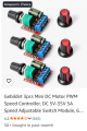
if you have bench power supply, set voltage and current limit low then gradually increase till full brightness. note the voltage V and current draw I. add at least 10-25 % to voltage and 25% to current, then pick PSU that can handle that. add series resistor to create voltage drop needed to handle the 10-25% boost we added earlier. using resistor linearizes LEDs a bit so that slight fluctuations in voltage do not result in massive current change. next get el cheapo PWM from Amazon or Temu or AliExpress to control the brightness. something like this will do
1793214425180.png
 
Top