Designing audio JFET front end for low THD+N

Thread Starter

rpschultz

Joined Nov 23, 2022
848
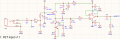
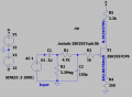
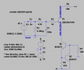
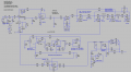
I've been working on an acoustic guitar preamp for some time now, here is one previous thread. The front end is similar to a Fishman Mini (attached). I have measured THD+N using REW and a Motu M4 on various prototypes, both thru hole versions use same JFET BJT arrangement as Fishman mini. SMD version(s) attempted to make it more compact and eliminate hookup wires since they can be a source of noise pickups for a JFET front end. But the THD+N is going up, not down.

  1. Original thru hole (Blue), PN4392 and 5088s - 0.058% THD+N
  2. Next thru hole (Red), PN4392 and 5088s - 0.042%
  3. SMD v1.0, J113 and SS8050 - 0.028%
  4. SMD v1.1, MMBF4392 and BC847C - 0.063% (all 4 measured at same level)

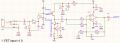
The above measurements are the entire pedal, but for the SMD versions I can measure just the JFET and Buffer portion, same as schematics below:
  1. v1.0 power board only - 0.0096% THD+N
  2. V1.1 power board only - 0.059% THD+N

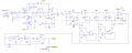
Even though v1.0 is the best, it is clear to me that for v1.0 and v1.1 I didn't know what I was doing with biasing the JFET for lowest noise. I have LTspice and have various simulations, but I am a novice and don't understand how to do noise measurement analysis . So I'm looking for an education on how to properly bias and design a JFET audio front end so it produces the lowest THD+N. I'd love to get THD+N down to 0.01%. Other circuit suggestions are welcome too, but I suspect the JFET is the main thing. The circuit below is roughly 1/2 of the total circuit, the other 1/2 has lots of RC filtering, EQ, etc, recent pictures of v1.0 here.

Vcc, Vee are +-15v using TEC 2-0923 DC-DC converter from 9v.
1783730089618.png
1783730131341.png
 

Attachments

Last edited:

Ian0

Joined Aug 7, 2020
13,172
In theory, the higher the Gfs the greater the feedback, the closer the gain is to unity, and the lower the distortion.
Have you tried it with a simple resistive load to 0V or to V- just to make sure that the bipolar current sink isn’t causing the problem?
If low THD is your object, then a JFET op-amp will beat a discrete JFET circuit every time. As you have other op-amps in circuit, do you have a particular reason for using the discrete buffer?
I’ve used one before, but only because I needed one extra section on my TL074
 

Thread Starter

rpschultz

Joined Nov 23, 2022
848
I wondered about a jfet op amp, using an OPA1652. I tried to model it's THD+N in spice and compare with the discrete jfet, but I'm not succeeding. I had AI help me with the LTspice code, but I think it was chasing it's tail, never got it to work right. Seems that there should be a simpler way to measure distortion or noise or both.

1783855456736.png

Similarly the transistor circuit.
1783856304676.png

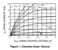
Back to the transistor, I've read you get lowest distortion when the transfer curve is linear. I think part of the problem is that Vds is pretty high, almost 14v. The below curve suggests I need to lower Vds and get Id in the 1-5 mA range. Currently it's 1.3 mA above with the 100R.
1783856047190.png

Thanks for the help!
 

MrChips

Joined Oct 2, 2009
34,974
Back to the transistor, I've read you get lowest distortion when the transfer curve is linear. I think part of the problem is that Vds is pretty high, almost 14v. The below curve suggests I need to lower Vds and get Id in the 1-5 mA range. Currently it's 1.3 mA above with the 100R.

Thanks for the help!
You are misinterpreting the meaning of linear. It is not where the curve is flattest.
It is where ΔID/ΔVGS is constant.

1783859630050.png

Try ID = 5 mA @ VDS = 0.8 V, VGS = -0.6 V
or ID = 5.5 mA @ VDS = 1.2 V, VGS = -0.6 V
 

Ian0

Joined Aug 7, 2020
13,172
Have you read Merlin Blencowe’s books? I know they are about valves not JFETs, but what you are designing is no different from a cathode follower.
 

Thread Starter

rpschultz

Joined Nov 23, 2022
848
Merlin Blencowe
Yeah I've messed with tube amps before, skimmed through one of them. Although, you may see the similarities between a cathode follower (I modded a Blues Jr. in that way before) and a JFET, but I'm not there yet. Thanks though.
 

Thread Starter

rpschultz

Joined Nov 23, 2022
848
OK how about this? Id = 2mA, Vsd = 7.9.
This single-sided JFET arrangement is simpler than the original dual sided JFET-BJT configuration.
Does a single sided work for audio? Is there a preference?

1783886102978.png

Id: 2.01e-03
Vgs: -5.03e-01
Vds: 7.86e+00
Gm: 1.65e-02
Gds: 5.89e-05
Cgs: 6.21e-12
Cgd: 3.12e-12
 

Ian0

Joined Aug 7, 2020
13,172
Should work. You can take an almost unity gain signal off the source, or a signal with a bit of gain off the drain.
 

Thread Starter

rpschultz

Joined Nov 23, 2022
848
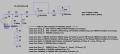
Having AI help me calculate THD+N on the single sided version (post #10).
****
.tran 0 50m 40m 1u
.option plotwinsize=0
.four 1000 V(n006)

.noise V(n006) V3 dec 200 10 100k
*********
THD ≈ 0.17 %
Noise ≈ 8.5 nV/√Hz
(then do some math)
THD+N ≈ 0.17 % for single sided version of 2SK3557
---------------------------------------------------------------------------------------
Then I went back to the JFET+bjt network (post 1, v1.1) and used the 2SK3557-6:
1783894328021.png

Here the operating points are different:
Id: 1.33e-03
Vgs: -5.69e-01
Vds: 1.43e+01
Gm: 1.46e-02
Id =1.3mA seems good. Vds is a lot higher but under the 15v limit. Vgs is near the audio center.

THD ≈ 0.001041 % (way lower than single sided config)
Noise ≈ 9.7 nV/√Hz
(then do some math)
THD+N ≈ 0.0011 % for 2SK3557 + BJT network

Wow. 2SK3557-6 in BJT network is a LOT lower THD+N than the single sided version. Makes sense why Fishman used the BJT network on the original 2N4392.
------------------------------------------------------------------
Then I went back and looked at the J113+BC847, a mashup of v1.0 and v1.1. THD was actually lower, but noise was MUCH higher.

Noise curve for 2SK3557+BJTs, very flat in audio range, 9.7 nV/√Hz
1783895175631.png

Noise curve for J113, not flat and much higher magnitudes as well. Roughly 50x noisier.
1783895144823.png

Doing some AI math, J113+BJT config
THD ≈ 0.000193% (lower)
Noise ≈ 0.5 µV/√Hz @ 1kHz (much higher)
THD+N = 0.006%
-------------------
So the 2SK3557+BJTs is 6x better THD+N than the J113+BJTs.

This was fun. Hope I did it right.
 

Thread Starter

rpschultz

Joined Nov 23, 2022
848
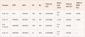
Here's a table of results. I have 2 prototypes (full pedal not just JFET front end) and measured both of them in REW. The 2nd line v1.1 REW measurement was SPOT on my spice simulation. This gives me great confidents to modify v1.1 (line 3) and maybe modify again (line 4) to measure again before I print v1.2.

1783952568495.png

1783952799675.png

.op for line 4:
Id: 6.28e-04 0.6 mA
Vgs: -6.31e-01
Vds: 1.42e+01 14.2 v
Gm: 1.00e-02
 

Ian0

Joined Aug 7, 2020
13,172
I don’t tend to give to much weight to SPICE’s distortion analysis. SPICE says I can design power amplifiers with less than 2ppm distortion, and I know I’m not that good!
 

Thread Starter

rpschultz

Joined Nov 23, 2022
848
I don’t tend to give to much weight to SPICE’s distortion analysis. SPICE says I can design power amplifiers with less than 2ppm distortion, and I know I’m not that good!
Yeah grain of salt. But it's striking to me that a larger circuit like that can be simulated so close to what prototypes measure to.
 

crutschow

Joined Mar 14, 2008
38,599
SPICE says I can design power amplifiers with less than 2ppm distortion, and I know I’m not that good!
What circuit is that?
Never seen anything that low.
The audio amp and oscillator circuits I've looked at with LTspice generally measure from a few tenths to several percent harmonic distortion using the .four command.
 

Ian0

Joined Aug 7, 2020
13,172
What circuit is that?
Never seen anything that low.
The audio amp and oscillator circuits I've looked at with LTspice generally measure from a few tenths to several percent harmonic distortion using the .four command.
Show everyone my 2 ppm power amp? Never! It’s top secret!
I’ve not got access to my computer at the moment (Due to being in hospital with a chest infection), but I’ll post it as soon as I can ( but not on @rpschultz ‘s thread) as I always value the opinions of my peers. I think it has one too many over-simplified over-perfect SPICE component models in it.
 

Ian0

Joined Aug 7, 2020
13,172
Have you explored all of Om-Semi’s offerings? I think that there are so relatively cheap dual devices.

Have you tried using a second FET as the constant current sink? Like an upside-down cascode?
 

Thread Starter

rpschultz

Joined Nov 23, 2022
848
Have you explored all of Om-Semi’s offerings? I think that there are so relatively cheap dual devices.
Have you tried using a second FET as the constant current sink? Like an upside-down cascode?
One upgrade I have found recently was replacing TL074's with MC33079, from OnSemi. For the EQ portions of this circuit it will have lower noise, the high impedance of the TL074 isn't necessary since it has the JFET and NE5532 front end.

I'll have to simulate your 2nd JFET idea.
Thanks!
 

Ian0

Joined Aug 7, 2020
13,172
One upgrade I have found recently was replacing TL074's with MC33079, from OnSemi. For the EQ portions of this circuit it will have lower noise, the high impedance of the TL074 isn't necessary since it has the JFET and NE5532 front end.

I'll have to simulate your 2nd JFET idea.
Thanks!
MC33079 is a very good audio op-amp, but it’s bipolar, not FET. I always preferred the LF351 to the TL071 (though I‘m not sure that they aren’t the same thing these days). There’s a lot of decent JFET op amps out there these days. For your Project I’d always preferred JFET over MOSFET because of the better 1/f noise corner.

For the dual JFET circuit, JFET #2 has its gate connected to ground and a resistor between source and ground to set the current. Source of the input FET connects to its drain, and that’s your output terminal (but you’d probably already worked that out)
 
Top