LEDs are driven by constant current sources, therefore they don't need short-circuit protection. A constant current source will not be damage by a short circuit.
LEDs are driven by constant current sources, therefore they don't need short-circuit protection. A constant current source will not be damage by a short circuit.
Hi, in my case it is a power supply with a short circuit protection. The idea is that I will have multiple such devices chained in parallel. Then, if one of the devices shorts (because LEDs are outside, anything may happen), it will bring down the power supply and all the devices in bulk. What I want is a smart device that will switch it's LED power off on short, give a signal to CPU and the CPU will send an error to my server
they are not... you can measure them and you will see that they are in the ballpark.
i see no details on actual load (missing part number / datasheet for your LED specimen). did not know what power LED.
LEDs are current driven devices and i do not see what is setting LED current in your case (you need to ensure this is checked)
assuming the "LED LAMP" is a device that includes internal current regulation, your circuit makes sense. since the LEDs are to be used outside and connecting wires are likely long, using overcurrent protection also makes sense. but you want something that trips reliably and a bit higher than actual load current.
i do not know if your device is really 12V and 1.2A. but if that is the case, without looking for another OpAmp or redesigning much, you can just follow suggestion from crutschow and increase value of the R1.
it changes sense voltage/offset voltage in your favour and that is both low cost and least effort solution. optionally use comparator instead of opamp. comparators are both faster than opamp and have smaller offset.
they are not... you can measure them and you will see that they are in the ballpark.
i see no details on actual load (missing part number / datasheet for your LED specimen). did not know what power LED.
LEDs are current driven devices and i do not see what is setting LED current in your case.
assuming the "LED LAMP" is a device that includes internal current regulation, your circuit makes sense. since the LEDs are to be used outside and connecting wires are likely long, using overcurrent protection also makes sense. but you want something that trips a reliably and a bit higher than actual load current.
i do not know if your device is really 12V and 1.2A. but if that is the case, without looking for another OpAmp or redesigning much, you can just follow suggestion from crutschow and increase value of the R1.
it changes sense voltage/offset voltage in your favour and that is both low cost and least effort solution. optionally use comparator instead of opamp. comparators are both faster than opamp and have smaller offset.
Q1 Rds_on is some 8mOhm
your PSU is high power so internal resistance will be tiny as well.
R1 is small value (was 8mOhm before suggestion to increase it to 40mOhm)
your biggest issue is wire resistance (depends on wire size/length).
suppose you use AWG16, 15feet long, we are talking about 60mOhm.
add those together and you are right around 100mOhm that i guessed.
for not knowing psu, load, wire size or wire length, i would say that is a pretty reasonable guess.
Q1 Rds_on is some 8mOhm
your PSU is high power so internal resistance will be tiny as well.
R1 is small value (was 8mOhm before suggestion to increase it to 40mOhm)
your biggest issue is wire resistance (depends on wire size/length).
suppose you use AWG16, 15feet long, we are talking about 60mOhm.
add those together and you are right around 100mOhm that i guessed.
for not knowing psu, load, wire size or wire length, i would say that is a pretty reasonable guess.
Hi, you are pretty close. I have European standard cable of 1.5mm2 (AWG16 is 1.3mm2) and the cable length will be around 25 feet. So yes, there will be some cable resistance.... Now I think I could have designed for 24volts, but some hardware for the project is bought already, so will stick to 12V
1. What is the overall system architecture? One microcontroller controlling Multiple LEDs? or LED strings?
2. If one controller per LED drive, then move logic into controller.
3. Is PWM drive intended?
4. Suggest using separate supply source for controller/logic, and LED drive, so that shorted "load" doesn't affect controller/logic function.
5. A TL431 configured as comparator can be used instead of LM358(s).
6. The NAND gate inputs will "float" when the MCU boots, so you will need to initialize the FF state at powerup.
1. What is the overall system architecture? One microcontroller controlling Multiple LEDs? or LED strings?
2. If one controller per LED drive, then move logic into controller.
3. Is PWM drive intended?
4. Suggest using separate supply source for controller/logic, and LED drive, so that shorted "load" doesn't affect controller/logic function.
5. A TL431 configured as comparator can be used instead of LM358(s).
6. The NAND gate inputs will "float" when the MCU boots, so you will need to initialize the FF state at powerup.
1. The device is [ESP32 + motor + LED mosfet + other circuitry, like motor bridge, 3,3 V buck, etc] <- enclosed in IP65 + LED (outside). I plan 12-13 such devices. All they will contact the server using MQTT. They are connected in parallel on 12V supply line. LED is COB 20cm stick
2. Yes, ESP32 is managing motor and LED, per device. It talks to the server.
3. No. Motor opens and closes decoration tile on the house exterior. It kinda "hides" the LED device when it is off. It works for 5 seconds while opening or closing. JGY370 with 2 RPM, with hall sensors.
4. It is not a life saving device. It will provide a light for a house exterior. I want a simple design. I will put capacitors, maybe they will provide sufficient power to the CPU if one of devices tries to short circuit power line (for I hope very short time period)
5. Thanks! Will try to look and see if I can use it.
6. ESP has outputs, some have high, some have low at the boot time. Thanks for reminding this. I will need to see which outputs I need to connect to avoid led "blink" at the start
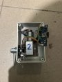
I have a working prototype already (using ESP8266, older CPU version), attached few pictures from the real PoC so I could give a real situation overview.
Hi, I am designing smart LED light device that will be used outside. It will have a CPU (ESP32) and other components.
I want to design short circuit protection for LED (the circuit is below)
Requirements I have:
High side switch (I want +12V to appear on LED only when it should)
CPU gets notified if short circuit happens (there will be many such devices, I want to know which is faulty)
Very low resistance shunt (R1 0,008 Ohm), because I do not want additional heat, as device will be packed in a hermetic box
How it works:
The latch made from elements 74LS00 memorizes the state of short circuit.
Before switching LED on, CPU makes short low pulse to the latch input 4. Latch gets high in output 6. Now it is ready to switch the led on.
CPU then sends high signal to U2A input 1. Both high inputs gives LOW on U2A output and MOSFET switches on.
U1A - first stage of op amp amplifies normal LED current drop on R1 (~5 mV) 300 times. Let it be up to 2volts - I leave an error margin here. The version of LM358ADT has 2mV offset, I think it is OK for error margin.
U1B - the second stage compares the amplified voltage against a reference ~8V and if the first stage sends bigger voltage (due to short circuit, current shall rise few times, above 3-5 Amps), output of U1B goes low, latch output 6 goes low, gate U2A output goes high and it switches off the MOSFET
LED is switched off and U1B is high again. Without the latch, the power to the LED would be sent again. It would start to oscillate, but the latch remembers the state and power to the LED stays shut off.
CPU will receive HIGH level in "CPU LED shorted" input.
My questions:
Is it not overcomplicated?
Will 2 stages of op amps be too slow? 74HC00 has nanosecond switching time, but LM358 sadly has ~25 microseconds per stage if I am correct.
Hello,
Just sharing that I'd go with a monolithic solution instead of Q1 and external components
(many LED drivers out there have OCP detection
with I2C programmable thresholds and other protection features)
For me it's simpler, cheaper, faster, easier to troubleshoot (one component only), etc.
Hello,
Just sharing that I'd go with a monolithic solution instead of Q1 and external components
(many LED drivers out there have OCP detection
with I2C programmable thresholds and other protection features)
For me it's simpler, cheaper, faster, easier to troubleshoot (one component only), etc.
I have bought a few and they indeed drive ~900mA. I have built one prototype and it seems working quite well. Not sure how they age. Will see. Internally it is tiny led diodes put over some surface and a silicon coating is over them. On the bottom all the structure is put on an aluminium stick, about 1mm thickness, so heat transfer is quite ok.
so they are just COB with no driver or current control. that means even slight change in supply voltage will have significant effect on current and brightness.
so they are just COB with no driver or current control. that means even slight change in supply voltage will have significant effect on current and brightness.
Hi, yes. Fits my design for now. I have tried them with ~0.5 volt drop and the brightness almost does not change, which means they should work in my light devices. They emit some amount of heat, but I have mounted them inside a metal U shape extruder and it dissipates the heat. I would say, first my purpose for now
Please consider that with the circui shown in post #1, there are actually THREE shorted circuit possibilities: #1: the positive feed to the LED connects to some "ground" circuit. #2, the connections to the LED (feed to LED return circuit) become shorted to reach other. (this has been discussed), and #3, the return circuit from the LED becomes connected to some "ground" circuit, bypassing the circuit back to the current sensing resistor. In my expperience all three are unfortunately possible. All three would prevent the LED from lighting.
There is also another fault mode of a broken circuit, not previously mentioned.
My point being that a detection system that can sense different fault modes might be woth some consideration.
Please consider that with the circui shown in post #1, there are actually THREE shorted circuit possibilities: #1: the positive feed to the LED connects to some "ground" circuit. #2, the connections to the LED (feed to LED return circuit) become shorted to reach other. (this has been discussed), and #3, the return circuit from the LED becomes connected to some "ground" circuit, bypassing the circuit back to the current sensing resistor. In my expperience all three are unfortunately possible. All three would prevent the LED from lighting.
There is also another fault mode of a broken circuit, not previously mentioned.
My point being that a detection system that can sense different fault modes might be woth some consideration.
Hi, I did not think about that ... I hope to avoid #1 and #3 by sealing the device into the box (do not remember now, smth like IP68)
Will try to consider..

 Facebook
 Google
 GitHub
 Linkedin