Design amplifier with gain for 1000

LvW

Joined Jun 13, 2013
2,051
Example,for frequency 50 kHz and 30MHz output amplitude should amplify to 20 V.
Independent on the implemented gain these data require a slew rate of app. 3600V/µs. (The unit as mentioned in the posting above provides only 2000V/µs).
 

Thread Starter

xw0927

Joined Dec 19, 2010
114
No, you need a supply voltage greater (by a couple of volts typically) than the peak output voltage. By the way are you wanting 20 volts RMS, 20 volts peak or 20 volts peak-to-peak?

Here is an amplifier that has the best high frequency, output voltage swing and drive that I have found:

http://www.ti.com/product/ths6022

Be warned that this is a surface mount part and _very_ demanding on circuit board layout and power supply bypassing.
Hi RichardO,

20V peak to peak..thanks,i will have a look to that chip.:)
 
No, you need a supply voltage greater (by a couple of volts typically) than the peak output voltage. By the way are you wanting 20 volts RMS, 20 volts peak or 20 volts peak-to-peak?

Here is an amplifier that has the best high frequency, output voltage swing and drive that I have found:

http://www.ti.com/product/ths6022

Be warned that this is a surface mount part and _very_ demanding on circuit board layout and power supply bypassing.
Woulde be up to 25Vp-P on this one actually.
But a very good device with excellent data.

If unfamiliar with using SMD, buy a SMD to DIL buard to mount this one on, and the rest is quite easy.
 

Thread Starter

xw0927

Joined Dec 19, 2010
114
To me, it would be helpful if you would summarize your requirements
(gain, maximum frequency, maximum output amplitude, power supply restrictions).
Hi LvW,

gain =100
maximun frequency= 40 MHz
maximun output amplitude = 20 Vpp
power supply= for my microcontroller is 5V supply

Thanks
 

Thread Starter

xw0927

Joined Dec 19, 2010
114
5V for the amplifier (single supply)?
Hi LvW,

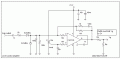
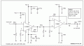
nope,i think can connect up to 15V for the amplifier..and I have found a circuit (do refer to attachmnet),
For the Ca 3130, can i replace it with the voltage divider circuit? and CLC 5523 I am not sure whcih chip can replace it,as this chip is obsolete,so I am going to find 1 chip to replace it and I will replace the TI6002 with THS 6022.

thanks
 

Attachments

LvW

Joined Jun 13, 2013
2,051
xw0972,
I have no experience with the referenced units.
By the way - I forgot to ask what your requirements are regarding input and output impedance. That means: Why not use two discrete transistor gain stages in series?
I am afraid, it will be a problem to find an opamp that allows a gain of 100 with 10V peak output at a frequency of 40 MHz.
Did you check already current-feedback amplifiers? I think - if any, they provide the best chance to fulfill your requirements.
 

Thread Starter

xw0927

Joined Dec 19, 2010
114
xw0972,
I have no experience with the referenced units.
By the way - I forgot to ask what your requirements are regarding input and output impedance. That means: Why not use two discrete transistor gain stages in series?
I am afraid, it will be a problem to find an opamp that allows a gain of 100 with 10V peak output at a frequency of 40 MHz.
Did you check already current-feedback amplifiers? I think - if any, they provide the best chance to fulfill your requirements.
input of amplifier will be connected to the output of the AD9850 chip module and then the output impedance will let floating,yeah,i checked the amplifier ady,i think THS 6002 is suitable.
 
Top