Delaying Sine/Square Signal

Thread Starter

musicismagic

Joined Jul 24, 2017
10
Hello everyone!

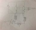
I need to delay a signal to use as the control signal for a full-bridge inverter, so that the original signal controls one half of the H bridge and the delayed signal controls the other half, creating a modified sine wave output.

I cannot figure out a way to delay this signal. I will be using a sine wave and then I will send it through an comparator op amp to create a square wave to control the switches. I need to delay this signal at either of these stages, depending on which is easier to delay (a sine wave or a square wave).

What would be the easiest way to do this, without the need for computer programming or anything like that?

Thank you!
 

AnalogKid

Joined Aug 1, 2013
10,987
What would be the easiest way for us to know the amplitude and frequency of the signal, and the amount of delay you need, without asking 20 questions or anything like that?

ak
 

Thread Starter

musicismagic

Joined Jul 24, 2017
10
What would be the easiest way for us to know the amplitude and frequency of the signal, and the amount of delay you need, without asking 20 questions or anything like that?

ak
I guess I can describe it? The amplitude is 9V. It is a 60Hz signal that should be delayed about 3 ms.
 

Alec_t

Joined Sep 17, 2013
14,280
A so-called 'modified sine wave' inverter generally doesn't require any sine wave input. It simply provides an out put which cycles through +,0,-,0,+,0,-,0,+,0 ........ So delaying a sine-wave signal may be unnecessary.
Can you post a schematic for your inverter?
 

Thread Starter

musicismagic

Joined Jul 24, 2017
10
A so-called 'modified sine wave' inverter generally doesn't require any sine wave input. It simply provides an out put which cycles through +,0,-,0,+,0,-,0,+,0 ........ So delaying a sine-wave signal may be unnecessary.
Can you post a schematic for your inverter?
I just attached a very rough sketch of what I am trying to describe.
 

Attachments

Alec_t

Joined Sep 17, 2013
14,280
If you're going to use a sine-wave-source-and-comparator approach, then you could use one comparator with a positive reference for deriving the gate drive for one half bridge and use a second comparator with a negative reference to derive the gate drive voltage for the other half bridge.
 

Thread Starter

musicismagic

Joined Jul 24, 2017
10
Yes that was going to be what I would do in the end if I wasn't able to delay it, but ericgibbs's solution seems just perfect!

So just needed an RC filter, and the time constant is the delay? That is simple enough! Thank you!
 

MrAl

Joined Jun 17, 2014
11,389
Hi,

It looks like you are trying to create a modified sine wave output for the bridge.
In that case, if you cut the sides of the square wave by a certain amount, you can eliminate one of the harmonics completely, and think that is the goal of today's inverters. Since the third is the worst, it is not a bad idea to concentrate on that one. That would mean a fixed delay of a certain value. With that value the third harmonic disappears and makes the waveform a little more palatable for the load electronics.
If you are interested i will look up the delay required.

Actually this was somewhat easy to remember, however, there is either two delays or just one delay required for the whole 1/2 cycle square wave and it sounds like you were close already.

The delay is: 2.77ms which is close to your original 3ms.
This is for the leading edge ONLY however. The falling edge must follow the original square wave falling edge.
This means you should say add a diode across R12 to Eric's circuit that will discharge the cap faster than it charges for example. The delay must occur for both half cycles as well.
 
Last edited:

Thread Starter

musicismagic

Joined Jul 24, 2017
10
Hi,

This is for the leading edge ONLY however. The falling edge must follow the original square wave falling edge.
This means you should say add a diode across R12 to Eric's circuit that will discharge the cap faster than it charges for example. The delay must occur for both half cycles as well.
MrAl, I don't know if I completely understood this correctly.

This is what I did, but it looks a lot less sinusoidal than it does without the diode?
 

Attachments

MrAl

Joined Jun 17, 2014
11,389
Hello again,

Well that's an entirely different circuit now :)
If you get the right output without the diode then dont use the diode :)

Perhaps you can show the output wave when you DONT use the diode.
It should look like something in your #8 post.

___HHHHH___LLLLL

H=+1
L=-1
and scaled to suite.
 

Thread Starter

musicismagic

Joined Jul 24, 2017
10
Yeah it looks pretty nice without it, but I will have to keep the diode idea in mind! It will probably be useful at some point :) Thank you for your help!
 

Thread Starter

musicismagic

Joined Jul 24, 2017
10
Hey I'm back! I've been trying to explore the Bessel filter as another way to delay since it can group delay. The equations I've found online have confused me and I don't see how to design a specific delay with them.

Would anyone be willing to give me a quick crash course on group delay with Bessel filter? Thank you!
 

simozz

Joined Jul 23, 2017
125
Hello,

Every analog filter leads to a group delay in the time domain.
The Bessel filter's parameter is the delay and not the cutoff frequency.
If you are interested on this specific topic, the best text resource you can find for analog filters is the book by A. Valkenburg.

simozz
 
Last edited:

AnalogKid

Joined Aug 1, 2013
10,987
According to the drawing in post #8, you are trying to delay a square wave, not a sine wave. That is a very different, and much easier problem. One resistor, one capacitor, one exclusive-OR gate. With a non-T CMOS gate, such as an HC series part as opposed to an HCT part, the positive edge and negative edge delays should track nicely.

ak
 
Top