Delay off Relay controlling power tool and dust extractor

Thread Starter

paul28

Joined Aug 27, 2024
18
Hi,

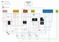
Can some one tell me if I have the terminal wiring in the picture below correct. I cannot tell from the instructions for the current sensor whether K1 should be connected to A1 or S terminals of the timer relay and K2 to S or A1. I am not sure whether it is K1 or K2 that sends the trigger signal, when the current sensor is activated, to the timer relay. Earth wiring not shown for the circuit. Blue wiring represents common or neutral and brown wiring represents live.


GRT8-B1 is a delay off timer relay.

The principal is that when the power tool is switched on the dust extractor starts and when the power tool is switched off the dust extractor is turned off following a pre-set time delay programmed in the timer relay.

Hope all makes sense and thank you in advance for any help with this that is given.

1724943750149.png
 

crutschow

Joined Mar 14, 2008
38,316
According to the diagram below, you need a neutral connection to A2, and make the dotted-line connection from K1 to S (CR4 generates the relay contact closure Trigger signal).
Otherwise I think your connections are correct.

So the CR4 relay contact closes when the power tool current is detected, which activates the Dust Extractor Socket.
When the the tool stops and the contact opens, the Dust Extractor power off is delayed by the setting of the delay module.

1724949975707.png
 
Last edited:

Thread Starter

paul28

Joined Aug 27, 2024
18
According to the diagram below, you need a neutral connection to A2, and make the connection from K1 to S (CR4 generates the relay contact closure Trigger).
Otherwise I think your connections are correct.

So the CR4 relay contact closes when the power tool current is detected, which activates the Dust Extractor Socket.
When the the tool stops and the contact opens, the Dust Extractor power off is delayed by the setting of the delay module.

View attachment 330443
Many thanks for your response.
 

Thread Starter

paul28

Joined Aug 27, 2024
18
Hi,

Following on from my earlier post I have now tried everything I can think of to solve my problem, but I have exhausted my logic and knowledge. I wouId appreciate some help to solve my shorting/tripping issue.

Function of the circuit

  1. The circuit diagram below has been designed to enable an automatic mode operation for a dust extractor, plugged into SPO 4, when a power tool such as a table saw, thicknesser, router, etc. is plugged into SPO 1, 2 or 3 is operated. This should allow the current that flows to be detected by the current sensing switch CR4 which then sends a signal to the timer delay relay CR2. On turning off the power tool the dust extractor at SPO 4 should continue to run for a pre-set time period set on the delay off timer relay CR2 and then switch off at the end of this period, e.g. say 10 seconds.
  2. The circuit is also intended/designed to allow power socket outlets SPO 1, 2 & 3 to be used without triggering the dust extractor and to allow the dust extractor to be run independently of power tool operation, i.e. in override mode. This is achieved by a direct power feed to SPO 1, 2 & 3 and bypassing the current sensor switch CR4 (Bypass mode) using Contactor CR3 and an override button PB6 respectively.

Operating Modes

Override mode
– allows dust extractor at SPO 4 to be operated independently of the current sensor switch CR4

Automatic mode – Dust extractor is controlled by operation of power tools

Stop mode – Does what it says on the tin and used to stop other modes operating

Bypass mode – not really a standalone mode but ensures the current sensor switch is bypassed when in override mode

Operation

Current flow is changed between current bypass mode and Auto mode by energising and de-energising the Contactor CR3 coil. This switches the flow of current from power tools at SPO 1, 2 & 3 from CR3 Terminal 1 to 2 to CR3 Terminal R1 to R2 and vice versus. If the coil is energised the current from the power tools flows via current sensor at CR4. If the coil is deenergised then said current from power tools bypasses CR4.

The coil is energised by pressing the blue momentary push button switch PB7. The CR3 coil is latched accordingly when PB7 is pressed. Well, that’s the theory anyway or would be if it worked, but the system is tripping at the breaker when PB7 is pressed and I cannot work out why.

The CR4 current detection coil should trigger the CR2 delay timer relay when current flows through CR4 detection coil.

Control indicator lights

Blue LED lamp L9 (Auto mode) - should be illuminated when the circuit is in Auto mode, i.e. Push button switch PB7 has been operated and CR3 coil is latched.

Orange LED lamp L2 (bypass mode) - when illuminated would indicate the circuit is bypassing the current sensing switch.

Red momentary push button switch PB5 when pressed acts to cut power to the CR1 coil and CR3-1 thus disrupting the latch of the CR3 coil and thus de-energising the CR3 coil and stopping power to Blue LED lamp L9 and SPO 4. Red LED Lamp L2 and orange LED lamp L2 are illuminated.

Override is to allow independent operation (non-auto) of the dust extractor and can be actioned by pressing green momentary push button PB6 which energises CR1 coil which is then latched.

Latching of coils is indicated by purple circuit lines on the circuit schematic diagram below.


What is working and what is not:

When the power is switched on at the mains breaker switch this is what happens:

Status of the circuit:

  • Orange bypass LED lamp L2 is illuminated,
  • CR1 relay coil is energised,
  • Green override LED lamp L1 is illuminated,
  • Power is available at SPO4,
  • Power is available at SPO 1, 2 & 3
Pressing PB5 (Red momentary button switch) changes the status of the circuit to:

  • CR1 relay coil is de-energised
  • Green LED lamp L1 goes off
  • Red LED lamp L8 is illuminated
  • Orange LED lamp L2 remains illuminated
  • No power is available at SPO 4
  • Power remains available at SPO 1, 2 & 3 as direct feed from L1-4

The above is all good and as expected.

The following is not expected:

Pressing PB7 trips the circuit, and the breaker switch trips to off.

Blue LED lamp L9 does not illuminate because the circuit trips.

Any help would be much appreciated to get this project finally working properly.
 

Attachments

Last edited:

crutschow

Joined Mar 14, 2008
38,316
Sorry, that's a neat wiring diagram, which is great for constructing it, but not good to readily understand how it works without redrawing it.

Schematics are the language of electronics so I would need a schematic that shows all the relay contacts and connections to determine what the problem might be.
 
Last edited:

Thread Starter

paul28

Joined Aug 27, 2024
18
Sorry, that's a neat wiring diagram, which is great for constructing it, but not good to readily understand how it works without redrawing it.

Schematics are the language of electronics so I would need a schematic that shows all the relay contacts and connections to determine what the problem might be.
After what is now several weeks finally I can reply to you.

For convenience I have restated below the function of the circuit design. Please note that I have redesigned the circuit and got rid of the tripping short circuit problem I was previously getting. This was due to me stupidly taking unused terminals with no load back to neutral.

As requested I have produced what I think is a schematic in the format you requested which includes terminal blocks to avoid more than one wire having to be connected to a given terminal. This also assists me in wiring up the control box. It should be easy enough to follow.

I have also produced a ladder diagram (see attached Excel file) and also managed to find a program online that simulates a circuit design and tests it. The simulation is working exactly as I envisaged but I am still getting issues in the real life circuit because it is not behaving as I designed it to like the simulation does. The simulation program is a bit short on components so I have had to improvise and use a push button (PT) and a relay to represent power tool operation current flow and the current sensing switch (CSS) respectively. Because the simulation programme does not specify terminal numbers for relays I have had to label the prints by hand.

I have included prints of the circuit simulation programme for each operation of the circuit to show the circuit works as it should and also an MP$ file link for the delay off operation of the Timer relay.

Function of the circuit

  1. The circuit diagram below has been designed to enable an automatic mode operation for a dust extractor, plugged into SO 4, when a power tool such as a table saw, thicknesser, router, etc. is plugged into SO 1, 2 or 3 is operated. This should allow the current that flows to be detected by the current sensing switch CSS which then sends a signal to the timer delay relay TR2. On turning off the power tool the dust extractor at SO 4 should continue to run for a pre-set time period set on the delay off timer relay TR2 and then switch off at the end of this period, e.g. say 10 seconds.
  2. The circuit is also intended/designed to allow power socket outlets SPO 1, 2 & 3 to be used without triggering the dust extractor and to allow the dust extractor to be run independently of power tool operation, i.e. in override mode. This is achieved by a direct power feed to SO 1, 2 & 3 before the Stop switch PB1 and bypassing the current sensor switch CSS (Bypass mode) using Contactor CR4 and an override button PB2 respectively

Components

  • Power Source: 240V AC single phase 50Hz, fused at 32A.
  • DTDP LY type relay with 240VAC coil and contact rating of 12A with 240 VAC or 28VDC model designation 28VDCJQX-13F LY-2 AC240V S x 2.
  • Contactor: Heschen HS1-63, 63A rated, 2-pole with terminals A1, A2 (coil), 1, 2 (main switching contacts Normally open), and R1, R2 (auxiliary contacts: R1-R2 is Normally Closed) x 1.
  • Delay Off Relay: Geyer GRT8-B1, 230V AC with terminals A1 (live), A2 (neutral), S (trigger), 15 (common), 16 (normally closed), 18 (normally open) x 1.
  • Current Sensing Switch: BEMG30NO with terminals K1, K2 (Normally Open) x 1.
  • 3 instantaneous Button Switches: PB1 Red (Off), PB2Green (Override), PB3 Blue (Auto).
  • Power Outlets: Power sockets 1, 2, 3 for power tools and Power Socket 4 for dust extractor.

Pictures of components.jpg

Operating Modes

Override mode
– allows dust extractor at SO 4 to be operated independently of the current sensor switch CSS

Automatic mode – Dust extractor is controlled by operation of power tools

Stop mode – Does what it says on the tin and is used to stop other modes operating when pressed

Bypass mode – not really a standalone mode but ensures the current sensor switch is bypassed when in override mode

Operation

Current flow is changed between current bypass mode and Auto mode by energising and de-energising the Relay CR4 coil via CR3. This switches the flow of current from power tools at SO 1, 2 & 3 from CR4 Terminal R1 to R2 to CR4 Terminal 1-2 and vice versus. If the coil is energised the current from the power tools flows via the current sensor CSS. If the coil is deenergised then said current from power tools bypasses the CSS.

For auto mode the coil is energised by pressing the blue momentary push button switch PB3. The CR3 coil is latched accordingly when PB3 is pressed.

The CSS current detection coil should trigger the CR2 delay timer relay when current flows through the CSS detection coil.

The circuit is designed to unlatch other mode relays when changing from override mode to Auto mode and vice versa. This is achieved by powering the relay latches via the other mode's relay.

Control indicator lights

Blue LED lamp L3 (Auto mode) - should be illuminated when the circuit is in Auto mode, i.e. Push button switch PB3 has been operated and CR3 coil is latched.

Orange LED lamp L4 (bypass mode) - when illuminated would indicate the circuit is bypassing the current sensing switch.

Red momentary push button switch PB1 when pressed acts to cut power to parts of the circuit to deenergise relay coils accordingly.

Override mode is indicated by LED L2(Green) lamp and allows independent operation (non-auto) of the dust extractor and can be actioned by pressing green momentary push button PB2 which energises CR1 coil which is then latched.

Coil latching is indicated by purple circuit lines on the circuit schematic diagram below.

Wiring Schematic:


Garage-auto-dust-extraction-rev1.jpg
Circuit Simulation programme prints:

In the circuit simulation prints below lights S1, S2 & S3 represent SO1, 2 & 3 in the circuit schematic. The dust extractor is represented by light DE.

Circuit Simulation Power Off.jpg


Circuit Simulation Power On.jpg


Circuit Simulation Power On Press and Hold PB1.jpg

Circuit Simulation Power On Press and Release PB2.jpg

Circuit Simulation Power On Press and Release PB3.jpg

The following link "Press PT Button.mp4" shows what happens in the circuit simulation when push button PT (Power Tool) is pressed and held for a while. On releasing PT which represents turning off power tools the count down starts and at the end of which the DE light representing the dust extractor motor goes off. Pink in the above simulation circuit prints represents a flowing current or illumination accordingly.

Press PT Button.mp4

The problems are:

On switch on at the PCB breaker CR1 is energised and L2 (Green) and L4 (orange) are illuminated. This is incorrect and should be L1 (red) and L4(orange) illuminated and no coils energised. CR2 indicator red light is on.

Pressing PB1(Stop) and holding down everything goes off. On letting go CR1 is energised and L2 (Green) and L4 (orange) are illuminated.

Pressing PB2(override) does nothing

Pressing PB3(Auto) illuminates L1(Red) and L4(orange) which is what you would expect when the system is powered on. CR3 does not latch which it should. L3(Blue) is only illuminated whilst PB3 is depressed, but not when released. CR2 red indicator light is on.

I have checked the physical wiring in the control box for continuity between all points and terminals and there is no continuity issue. There must be some miss wiring logic in my design that is not replicated in the simulation. I am not spotting. I don't see how the CR1 coil can be energised on switch on.

Any help will be gratefully received to solve the issues.
 

Attachments

Last edited:
Top