Delay circuit after SR Latch for motor direction control

Thread Starter

parhallenberg

Joined Dec 19, 2015
10
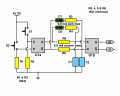
Hi! I've built an SR latch with 2n3904 transistors (see attached schematics; VCC 5V) to control two dc motors through an L298 board. The motors go in one direction, and change direction when "opposite" momentary switch is closed (i e the vehicle hitting a wall...).

Now I want to introduce a small delay (appx 1 s?) before the L298 seeing a rising signal, but no delay on falling (eg: J1 is high, J2 low. Momentary switch hit, L298 should immediately "see" J1 going low, but there should be a short time period before the signal from J2 is seen as high).

I think I should be able to do this with capacitors and resistors on lines between L298 and J1/J2, but can't get it to work... I would really appreciate some help!
 

Attachments

Tonyr1084

Joined Sep 24, 2015
7,853
From what I'm seeing, assuming the motor is positioned half way between full open and full closed (end of travel) both J1 & J2 will be positive. The motor won't run.

Now, momentarily close S1 and the motor will run (for sake of argument lets say) clockwise. As soon as S1 is no longer closed the motor will stop running.

If we assume that despite S1 opening the motor continues to run to the other limit switch (S2), when S2 closes then J2 goes to ground while J1 remains high, thus, running the motor in the opposite direction, counterclockwise.

The problem I see is that both "Momentary" switches are just that - momentary. Instead of using the circuit you built I'd opt for a latching 5 volt relay. It has two coils. One coil latches the contacts in one configuration while the other coil will latch it in the other configuration. Meaning that when one limit switch is hit the relay will latch (or unlatch) and you will be able to send the motor in the opposite direction. When the other switch is hit the other coil activates and unlatches (or latches), thus, sending the motor off in the original direction again. You won't need all the resistors or transistors. Likely the relay can handle more than the NPN transistors you are using.

I'm sure there's an electronic way of doing this, and if I press my mind just a little bit I can see using a D type flip/flop, using the "Set" and "Reset" inputs and the switches along with the transistors to toggle the direction of the motor.

As to why you want the one second delay - you'd need the transistor base and an RC circuit to give you the delay you're looking for.
 

Thread Starter

parhallenberg

Joined Dec 19, 2015
10
Hi Tony!

I'm so sorry, but it's seems I haven't made myself clear. J1 and J2 is connected to inputs on an L298 chip. My attached circuit "latches" the output so that one of J1/J2 is always high, the other one is the opposite (although which one is high is unknown/undefined at startup).

The momentary switches are mounted on the front and back of the vehicle, and the effect is that the vehicle reverses its direction when hitting a wall. This is working.

What I now need is suggestions on how to add something between each output (J1 and J2 in my circuit) and it's respective input on L298, to make the L298 see two low signals for some time (preferably 1 s) on every change of direction.

My proposition is to add a separate "circuit" after each of J1 and J2 that output low if the input is low, but if the input is high it outputs low for 1 s and then rise to high. I guess this is done with a capacitor and resistor but I'm not sure how.

Added: regarding current demands that's not a problem. The L298 takes care of that. My circuit is only signalling.
 

Tonyr1084

Joined Sep 24, 2015
7,853
One way to add delay to your circuit is to add a capacitor (positive lead) between R1 and the base of Q1 (negative lead to ground). The size of the capacitor will dictate how long it takes to charge sufficiently to send enough current to activate the change signal. HOWEVER, the momentary button needs to be held while the cap charges. If the button is let go before the cap has charged sufficiently then the charge will stop and Q1 will never turn on. One way around that problem would be to add another capacitor between S1 and R1 (positive to S1/R1, negative to ground). It will need to be substantially bigger in value so as to take a rapid charge the moment the switch is pushed, but when released its energy is fed through R1 into the second capacitor. (same for the other side of the circuit)

I'm not 100% sure of this but in theory it seems reasonable a solution. If anyone disagrees with me or finds problems with my solution (happens often enough) I'm sure someone will offer their advice. Though I've been dabbling in electronics for many years I'm CERTAINLY not the expert on this.

Let me bang out a picture for you to clarify. I'll edit my post when ready.
 

Thread Starter

parhallenberg

Joined Dec 19, 2015
10
I see! Problem is, I want the delay _after_ my circuit, that is after J1 and J2. But I should look at that capacitor/resistor suggestion.

One way to add delay to your circuit is to add a capacitor (positive lead) between R1 and the base of Q1 (negative lead to ground). The size of the capacitor will dictate how long it takes to charge sufficiently to send enough current to activate the change signal. HOWEVER, the momentary button needs to be held while the cap charges. If the button is let go before the cap has charged sufficiently then the charge will stop and Q1 will never turn on. One way around that problem would be to add another capacitor between S1 and R1 (positive to S1/R1, negative to ground). It will need to be substantially bigger in value so as to take a rapid charge the moment the switch is pushed, but when released its energy is fed through R1 into the second capacitor. (same for the other side of the circuit)

I'm not 100% sure of this but in theory it seems reasonable a solution. If anyone disagrees with me or finds problems with my solution (happens often enough) I'm sure someone will offer their advice. Though I've been dabbling in electronics for many years I'm CERTAINLY not the expert on this.

Let me bang out a picture for you to clarify. I'll edit my post when ready.
 

Tonyr1084

Joined Sep 24, 2015
7,853
The attached drawing shows two additional capacitors. The first one charges when the switch is pressed. The second one charges slowly through R1. As it reaches sufficient voltage current will flow into the transistor and turn it on. IF the switch is not held long enough the charge cap should supply sufficient current to continue charging the time cap.

Two suggestions: Lower the value of R1 to allow greater current through and instead of powering S1 from Vcc power it from the junction of the collector and R2. This will limit the charge rate of the Charge cap and prevent your switches from arcing excessively due to the drained nature of the Charge cap.

Also, the charge cap should have a bleed resistor in parallel to it to help it drain fast enough to be ready for the next cycle. It should drain through R1 & Q1 (base to emitter to ground), but a bleed resistor can hasten the drain.

For exact values you'll have to play with it a little. I might even do a spice simulation just to see IF my suggestion truly works. On LTSpice one can change values to see what works best and approaches most closely to what is desired. But I kind of have HDL's to do (Honey Do List).

Charge Time Cap.png
 

Thread Starter

parhallenberg

Joined Dec 19, 2015
10
Adding a (simplified) sketch of my circuit, which is working (ie it drives the motor one way, and on hitting one switch it reverses direction; hitting the other later reverses again). I tried putting a capacitor in series between J1 and pin 5 but that didn't work. Should I put it to GND instead? In that case, what value would I need and will I need a pullup/pulldown resistor somewhere to slow done the decay or charge of the capacitor?
Latch.png
 

Tonyr1084

Joined Sep 24, 2015
7,853
First, putting a capacitor in series does nothing for timing other than limiting what frequencies can pass through. Since this is a DC signal from a switch and a latching circuit, the cap between J1 & pin 5 will do nothing. If anything it will block the DC signal.

A capacitor (positive lead) connected to the J1 / pin 5 junction (negative lead to ground) will also do nothing. If anything, the capacitor will act as a filter to absorb any ripple in the signal.

IF you go from J1 to a resistor (lets call it R100) to pin 5 and connect the positive lead of a capacitor to the R100 / pin 5 junction with the negative to ground then you set up an RC circuit. (RC = Resistance/Capacitance) RC circuits are for timing (time delay). Depending on the value of the resistor and the capacitor you will achieve some sort of delay.

L298 might not tolerate a slow clock signal. The rise time of the positive going edge may be limited to a few milliseconds (but I guess at that). IF the case is that a slow clock pulse will be ignored you will fail to signal a reversal of direction.

Since J1 is a connector you can set the RC on your proto-board. You don't need to modify the L298 board. It can be built and added directly before J1. Remember, J1 is just a continuation of the wiring from your latching circuit.

I still think you're better off taking your time delay from the first set of switches as the way I drew my diagram. Of course, the choice is yours how to handle your engineering decisions. All any of us can do is give you pointers. This is my approach. Might not be the best approach - I certainly have lots to learn myself regarding electronics. But I believe my approach will work. At least I hope it does. I hate wasting other people's time and resources. The final decision is yours.
 

Thread Starter

parhallenberg

Joined Dec 19, 2015
10
Tony! Thank you so much for your time and thorough explanations! You have given me a lot of pointers. The last reply is also pretty much in line with a suggestion I got outside of the forum from a friend, I will post his circuit after confirming that it works.

One thing I don't understand though:
L298 might not tolerate a slow clock signal. The rise time of the positive going edge may be limited to a few milliseconds (but I guess at that). IF the case is that a slow clock pulse will be ignored you will fail to signal a reversal of direction.
The direction for L298 is set with two inputs where 10 gives one direction and 01 gives the reverse direction. 11 and 00 gives a brake - so the high pin has to stay high for any movement to happen. That's why I have the latching circuit to be able to reverse direction when the switch is hit. So from my understanding the L298 reacts to the high state, not the rising per se.
 

Tonyr1084

Joined Sep 24, 2015
7,853
Like I said, I don't know the specs on the L298. I DO know that some circuits that depend on a clock pulse (a high signal) is dependent on that signal rising at a minimum rate (or faster). In other words, some IC's are sensitive to clock pulse rise times that - oh, lets make up some numbers for the sake of understanding - a clock pulse (a high signal) that transitions from low to high in a period of time must rise and complete the transition from low to high within 5 micro-seconds. (again, keep in mind I'm making up numbers). If your clock pulse - driven by an RC circuit takes longer than 5 micro-seconds then the high signal will be ignored.

IF the L298 is sensitive to rise times then constructing your RC circuit will require some sort of buffer, something that snaps from low to high in an instant (so to say). An op-amp configured as a comparator will transition from low to high rather quickly.

As I'm sitting here I'm considering the use of a D Type Flip Flop instead of your latching circuit. The "Set" input will drive Q high (the complementary output /Q (called "Not Q") will always be opposite of Q) while "Reset" will drive Q low. Connecting Q & /Q to J1 & J2 will do the same thing your latching circuit will do. Adding the delay to the switch will be easy enough. You'll need to use both D Type FF's though. I'll have to think it through a little more but I'm sure I can come up with a diagram that will work.

How long a delay do you want before the motor reverses?
 

Tonyr1084

Joined Sep 24, 2015
7,853
OK, it seems I forgot to hit "POST" on my last entry. I've looked up the specs on the CD4013 CMOS Dual D type Flip Flop. I've come up with this circuit which I think you should be able to customize it for your purposes.

The outputs (Q & /Q) (cue & not-cue) can sink and source a max of 6.8 mA. So I wouldn't use any resistances on the outputs of U1a lower than 1KΩ. This will limit your current to 5 mA, which should ensure reliable service. You can use higher values than 1K but that's up to you. And for R5 & R6, certainly larger than 1K if you want your timing circuit to function properly. Diodes 1 & 2 are there to ensure the capacitors drain more quickly than they charge. So R5 & R6 need to be at least 5 times bigger. 10 times doesn't hurt either.

You'll need to calculate the time constant of each RC circuit and select a resistor and capacitor to give you the delay you seek. I'll leave the rest of the engineering up to you. Just keep in mind three things: Outputs Q & /Q can not sink or source more than 6.8 mA And the RC circuit needs to have resistance at least 5 times greater than the quenching resistors (R3 & R4). Finally, on the IC, ALL unused inputs (Clock & Data) need to be tied directly to ground. You CAN use a resistor - but that's not necessary.
 

Attachments

Thread Starter

parhallenberg

Joined Dec 19, 2015
10
Like I said, I don't know the specs on the L298. I DO know that some circuits that depend on a clock pulse (a high signal) is dependent on that signal rising at a minimum rate (or faster). In other words, some IC's are sensitive to clock pulse rise times that - oh, lets make up some numbers for the sake of understanding - a clock pulse (a high signal) that transitions from low to high in a period of time must rise and complete the transition from low to high within 5 micro-seconds. (again, keep in mind I'm making up numbers). If your clock pulse - driven by an RC circuit takes longer than 5 micro-seconds then the high signal will be ignored.
Thanks again for you thorough explanations, Tony! I see what you mean now; I hadn't thought about that at all. Turns out it didn't matter though, but I will definitely keep it in mind for the future. Seems like a schmitt trigger after the delay circuit would solve that problem, right?

Anyway. I got a sketch from a friend who suggested the same thing you were talking about in the 8th post. I have tried to implement it with a capacitor of 100uF and a resistor of 10k, and a 1n5818 in reverse parallell with the resistor. It works perfectly :)

So once again thank you so much for your time and your pointers. I'll attach my friends sketch for anybody who might find this post in the future. Credit goes to Korbinian Randl.
Delaycircuit.jpg
 
Top