Facebook
 Google
 GitHub
 Linkedin
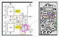
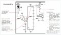
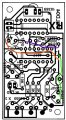
i had connected the LED On the emitter side. in addition, i had added hard wires to take of the error in my schematic drwg copied from You tube. pl. excuseConfigured like this?
View attachment 355174
Attachments
-
 72.1 KB Views: 6