DDS for an adjustable audio frequency PWM?

Thread Starter

electronice123

Joined Oct 10, 2008
350
Hi All,

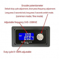
I bought a few XY-PWMs for a project. The interface and output PWM waveform is great, but the frequency stability is terrible. At 8kHz all 3 of them have an output freq that jumps around an 18Hz window. I need something that does the same job but does not deviate more than .05Hz.

What are me best options here?
DDS ic? Audio Synth?

I have other freq gens that work but...I need something small that will fit into my panel mount project.
 

Attachments

Last edited:

MisterBill2

Joined Jan 23, 2018
27,193
It does not appear, based only on the pin-out image, that there is an option for an external frequency source.
IF the TS is willing to provide us with the data sheet for that IC device then some of the really brilliant participants can provide a useful suggestion.
ALSO, neither a DDS nor an "audio Synth" are small or simple. So neither would be a good choice.
AND, GIVEN that we have no hint as to the TS technical abilities, this project may be excessively complex. The "information" line tells me nothing about the TS that would help.
This is by no means even close to a simple project. A great deal of programming skill and effort are needed.
 
Last edited:

Thread Starter

electronice123

Joined Oct 10, 2008
350
It does not appear, based only on the pin-out image, that there is an option for an external frequency source.
IF the TS is willing to provide us with the data sheet for that IC device then some of the really brilliant participants can provide a useful suggestion.
ALSO, neither a DDS nor an "audio Synth" are small or simple. So neither would be a good choice.
Datasheet attached.

Size and function of the small XY-PWMs are good, I just need better tuning resolution. It's used to drive an audio transformer at various frequencies and duty cycles.

CHATGPT has led me down the path of the AD9834, which I have zero knowledge in. I can build basic circuits and have designed 4 or 5 pcbs, and have done some basic Arduino projects. It seems there is no simple solution to what I need though. I'm considering hiring an engineer to do the following:

Design a variable freq PWM for 1Hz-12kHz, with a freq tuning resolution of .1Hz, and a duty cycle tuning resolution of.1%. It needs an LCD screen to display both and encoders for the adjustments.

I just need some recommendations on what path you guys would take or recommend. The XY-PWMs voltage and current in/out specs work great, I just need better tuning resolution.

Thanks for any help/ recommendations
 

Attachments

MisterBill2

Joined Jan 23, 2018
27,193
Certainly Bob is correct. and certainly the "PWM1 Circuit" drawing does not show any connection for an external frequency input. But on page 10 block diagram it seems that PIN #5 can be used for an external clock input.
And even more certainly, without seeing the data sheet there is no way to provide an answer. And now, looking at the 273 page "data sheet" it becomes clear that this device is not simple at all.

Have you tried all three of the internal time base sources??
If they are not good enough, probably a single external oscillator module in a DIP package, available from DIGIKEY will be adequate, but no clue about adjusting it.
 

BobTPH

Joined Jun 5, 2013
11,466
I’d use a microcontroller running at 48 MHz and some clever code to get the period within four clock cycles. I think it is possible with the fastest PIC24/33 series.
 
Top