DDS Buffer Amp

Thread Starter

Standisher

Joined Jan 16, 2015
156
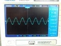
I recently bought a AD9850 DDS module which, when hooked up to an Arduino and a 16 x 2 LCD display performs very well. Output on the Oscilloscope is accurate and the waveform (upto about 25mHz) is good. The amplitude however, is not very good and falls off quite a lot at higher frequency (I get around 1V pk-pk at low frequencies but only abou 200mV pk-pk at higher frequencies).

I wanted to introduce a buffer-amp and came across a couple of designs on the internet which were claimed to work well with DDS modules. The designs were very similar. The only difference was that one had the addition of a transformer (using a tordoid wound with 12 turns and 4 turns) and a 0.1uf capacitor on the input. The author of this variant had also added a 47R resistor to the emitter of the gain stage to limit the gain. I chose to build up a circuit based on this design.

I have attached a schematic of the base design (minus the input transformer, input capacitor, and gain limiting 47R resistor) and also a photo of my circuit which includes the additions. The circuit actually seemed to work, momentarily but is now producing no amplification whatsoever (in fact it seems to reduce the amplitude of the signal!) . I though one of the transistors may have blown but I have changed them with no improvement and the replaced parts check out as good on a component tester. One concern I have is that the 4 turn side of the input transformer is effectively a dead short to ground; is that OK?

Is this design (or indeed the one without the input transformer/capacitor) likely to work or are both designs flawed (both authors claim their designs work perfectly)? Incidentally, I have thoroughly checked my layout; All connectivity is correct in accordance with the schematic, and there are no shorts (apart from the what seems to the meter be a short on the 4 turn winding of the transformer. Sorry for the long post.

bufferamp1.jpg rf_amp.jpg
 

ericgibbs

Joined Jan 29, 2010
21,439
hi,
Ran a LTS sim of the circuit digram you posted, it is not much good.?
Check the cct for accuracy.?
E

EDIT:

What frequency range and gain are you expecting from the amp.?
 

Attachments

Thread Starter

Standisher

Joined Jan 16, 2015
156
Hi @ericgibbs. I notice that you have added a 1K resistor on the input and a 50R resistor on the output. The result seems to be that you have obtained a significant amplitude increase at the output. Am I reading this correctly? (Oh, and does "cct" mean circuit?)
 

ericgibbs

Joined Jan 29, 2010
21,439
hi,
cct is a lazy way sometimes used instead of the correct spelling of circuit, sorry if caused a little confusion.
Do you have more technical information on the transformer, ie Inductance values.?

The circuit designer claims it will drive a 50R Load.

E

EDIT:
Please post a circuit showing all the components that are being used, ie: transformer connection, etc.
I can then update the LTSpice sim.
 
Last edited:

Thread Starter

Standisher

Joined Jan 16, 2015
156
hi,
Do you have more technical information on the transformer, ie Inductance values.?

The circuit designer claims it will drive a 50R Load.

E
I don't I'm afraid have any more info on the inductance values. The designer simply says that the transformer should be wound on a 37-43 toroid at a ratio of 12 tuns to 4 turns. This is the link I took the design I have built from. Thanks for your assistance.
 

bertus

Joined Apr 5, 2008
22,923
Hello,

You do not have a resistor of 47 Ohms in the emittor of the first transistor as in the given link.
This could cause the strange behaviour.

bufferamp-863x449.jpg

Bertus
 

ericgibbs

Joined Jan 29, 2010
21,439
hi S,
Adding the missing components as pointed out by @bertus has made a substantial improvement, using a best guess transformer.
It is important you always post the correct circuitry.;)

E
 

Attachments

Thread Starter

Standisher

Joined Jan 16, 2015
156
Sorry for the confusion. I posted one schematic (as this morning I could't easily capture the schematic that I built from) but did detail the components added as per the schematic posted by @bertus. The schematic posted by @bertus is the one I have built (as you can probably see from the picture I posted in my OP). I still wonder therefore why circuit doesn't work as I'm sure it is 100% in accordance with the schematic (famous last words, I know) ?
 

ericgibbs

Joined Jan 29, 2010
21,439
OK, no problem.
I know you said that the DDS output was 'good', but did you check the DDS out with the amplifier connected.?
Did you also check it over a range of frequency outputs.?
Sorry about so many questions, pity I cannot look over your shoulder.o_O
E

EDIT:
Check using an ohm meter the copper wire joints soldered to the PCB joints, the enamel can cause problems.
 
Last edited:

ebp

Joined Feb 8, 2018
2,332
37-43 is probably some vendor's designation for Fair-Rite type 43 ferrite in size 37 (0.37" OD). If I recall a company called Amidon or something like that sold Fair-Rite and Micrometals products on the hobby market.
To me, 43 is a strange choice for a broadband transformer. The permeability is quite low and the material is primarily used for suppression aps, but ...
The implication of the transformer is that the output impedance of the DDS board is quite high. The transformer is being used to improve the match to the low impedance of the common-emitter amp.

The emitter resistor in the first stage is important for DC bias point.

When you say the output of the DDS falls in amplitude at higher frequency - what freq? How are you connecting the oscilloscope? Do you have a schematic of the DDS output circuit?
 

ebp

Joined Feb 8, 2018
2,332
If the DDS output is being 'scoped directly, there isn't the slightest chance the amplitude at even moderate frequency is going to be good unless an active probe with 1 pF or less capacitance is being used. That is quite remarkably high source impedance - vastly higher than an oscilloscope probe's input impedance once you're up into the range of several MHz.
 
Last edited:

DickCappels

Joined Aug 21, 2008
10,661
The output is a current source (for those who need interpretation), which is pretty common for high frequency outputs.

The topology seems to be a strange choice for an amplifier following a current source, presumably shunted by the correct load resistor. An amplifier with a higher input impedance might have been a better choice.

Now that I got that off my chest, You said that it was working fine and then it stopped working fine. Perhaps rather than analyzing the circuit it would be a good idea to start looking to see what changed.

Any enamel remaining on the transformer lead(s) can cause this kind of intermittent connection. Try wiggling things in the circuit to see if wiggling or pushing on something brings back the "fine" operation.

You can use your scope to trace the signal. Voltage-wise the P-P signal at the base of the first transistor should be very small, the emitter signal similar in amplitude.

The collector of the first transistor should have a signal amplitude equal to the desired output signal, and the emitter should have a similar looking signal.

With a sufficient power supply (you are supplying the full 12 volts, aren't you?) the DC level at the emitter of Q2 should be near 6 volts.
 

Thread Starter

Standisher

Joined Jan 16, 2015
156
Hi Eric, Yes, it's difficult when you can't see what I'm doing, so I don't mind the questions one bit...just happy you are trying to help. Whilst the amp is connected, there is no change at the output of the DDS. Set at 20mHz, measured at the output of the DDS (whilst hooked up to the amp) I get 20mV pk-pk on the scope (blue trace on the attached pic). At the same time, I get just 9mV pk-pk at the output of the amp! So I seem to be doing a great job in attenuating the signal! I have checked over a range of frequencies from about 100 kHz to 30 kHz I with a similar outcome. At the lower end of this frequency scale however, the output of the DDS is a lot higher (about 4v pk-pk which falls off steadily after 2 Mhz) and I'm not sure the amp could deal with that, so I only intended switching in the amp at signals over 5 mHz.
 

Attachments

ericgibbs

Joined Jan 29, 2010
21,439
hi,
The AC freq analysis shows the circuit has no overall gain, for most frequencies it attenuates.
Can you post a link to the site where you got the circuit, are you sure its not meant to be a impedance converter down to 5oR.??
E
 

Thread Starter

Standisher

Joined Jan 16, 2015
156
hi,
The AC freq analysis shows the circuit has no overall gain, for most frequencies it attenuates.
Can you post a link to the site where you got the circuit, are you sure its not meant to be a impedance converter down to 5oR.??
E
Indeed it does seem to attenuate :( As I understand things, it is meant to be both an impedance converter and amplifier (as designed, with a gain of 3x or 10 x if 47R resistor is substituted with a link direct to ground). Here is the link to the circuit I used. As I said in my opening post it did seem to work, briefly.

@DickCappels I don't believe that enamel on the transformer leads is an issue as both windings give continuity on the connection points. I have been using the full 12V supply to the amp. I will now trace the signal & voltages as you suggest.
 

ebp

Joined Feb 8, 2018
2,332
12:4 and 4:1 is peculiar arithmetic.

Note that the transformer voltage "gain" at the actual 3:1 ratio is 1/3, so if the amplifier is supposed to have a gain of 3 the overall gain is 1.
 
Last edited:
Top