DC power supply setup for my workshop

Thread Starter

onlyvinod56

Joined Oct 14, 2008
369
Hi everyone,
Iam a student of graduation....interested in working with electronic & electrical circuits. basically i belong to Electrical background.

I want to set my personal room as my small workshop.
I need to gather each and every item ....from resistor to oscilloscope. Everytime i need to go to my college for testing any circuit.

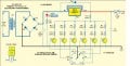
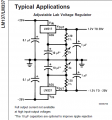
As a part of that, First i want to have a power supply. A DC power supply with adujastable facility for wide range of voltages +/- 24 max. Iam interested in having digital circuit. A small display to show the voltage.

Can anybody help me here please.
 

mik3

Joined Feb 4, 2008
4,843
If you are a newbie to this stuff it would be better to buy a ready one from a shop or from the internet. Search in google and in ebay.
 

SgtWookie

Joined Jul 17, 2007
22,230
Why don't you start with an easier and much less expensive project, like converting an ATX form-factor power supply to serve as a bench supply?

Google "ATX Bench Supply" for lots of ideas.

Starting from scratch and building your own supply may wind up costing a good bit more than just purchasing a used bench supply.
 

Thread Starter

onlyvinod56

Joined Oct 14, 2008
369
hi mik3
I can buy a power supply. But iam interested in doing this. Any suggestions with LM317, 7812, 7912, 7815, 7915....


Hi SGt.. Thanks for your suggestion i'll look through the google now.
I dont bother if it took so long time to design. Fropm here i want to knowthe concepts of SMPS also.

I want bulid simple power supply first then will go for smps
 

Thread Starter

onlyvinod56

Joined Oct 14, 2008
369
Hi, I got a schematic wen i am browsing.
see the attachment. LM317 is used here to give 3.3v, 6v, 9v, 12v, 15v.

Is there any IC to give negative voltages? like -3.3v, -6v, -9v.....
 

SgtWookie

Joined Jul 17, 2007
22,230
The LM337. It is very similar to the LM317, but for negative voltage regulation.

Go to National Semiconductor's website:
http://www.national.com
and find/download the datasheets for the LM117/LM317 and LM137/LM337 regulators.
There are quite a few application hints and typical application schematics.
 
Last edited:

Thread Starter

onlyvinod56

Joined Oct 14, 2008
369
thankyou sgt.
I have seen the article "ATX ~ bench power supply."
It is interesting. But directly i dont want to go for the smps.

thankyou
 

studiot

Joined Nov 9, 2007
4,998
Iam a student of graduation
What did you graduate in?
Well done and I admire people wanting to make their own.

Any electronic engineer worthy of the name should be able to produce a decent power supply. Unfortunately this comes with practise and quite a few destroyed components.
Further the engineer should be able to work with components that are readily (and cheaply) available rather than demanding specific components.

Since you are looking at linear power supplies be aware that they oscillate readily and can fail or be over noisy due to poor layout or earthing.

The transformer is usually easily the most expensive component so I should start here and see what you can obtain. To obtain +/- supplies you will need two windings or a centre tapped winding. Since all the power due to the difference in voltage between the maximum and that supplied to the load is discarded as heat provision for significant cooling is necessary. An old trick is to use multi-tapped windings and switch ranges to minimise this.

If you bench supply is mainly for op amps you might start with a fixed voltage while you are developing a better variable solution. ±12 or ±9 will cater for most eventualities. Many older hands will have built a box producing ±12 and +5 volts using fixed 78 / 79 series regulators. These work well enough to be going on with and are very cheap.

Your layout should establish a ground (or zero) point on one terminal of the reservoir capacitor. The transformer zero, the regulator, and the ouput should all be grounded (zeroed) directly here to minimise ripple.

Let us know your thoughts as to the components you can drum up for more detailed help.
 

mik3

Joined Feb 4, 2008
4,843
hi mik3
I can buy a power supply. But iam interested in doing this. Any suggestions with LM317, 7812, 7912, 7815, 7915....
It depends on the current requirements.
What is the maximum current you will need?

SMPS are more efficient than linear regulators when considering high currents.
 

Thread Starter

onlyvinod56

Joined Oct 14, 2008
369
Hi studiot.
Thankyou for your responce.

To obtain +/- supplies you will need two windings or a centre tapped winding.
yes iam also going for centre tap TF.

If you bench supply is mainly for op amps you might start with a fixed voltage while you are developing a better variable solution. ±12 or ±9 will cater for most eventualities. Many older hands will have built a box producing ±12 and +5 volts using fixed 78 / 79 series regulators. These work well enough to be going on with and are very cheap.
exactly. mostly my circuits are analog. But i want to use DVM for display. so, i plan to use LM317. Iam expecting that i'll get the desired voltage.

As sgtwookie suggested, the combination of LM337 and LM317 is the simple one.


see the attachment. i will use a 10k pot instead of the arrangement for pin 1 of LM317. Can u update the circuit for LM337.

Thankyou studiot.
 

Attachments

SgtWookie

Joined Jul 17, 2007
22,230
The 6-position rotary switch selectively turning on one of six PNP transistors to select the voltage by the resistance to ground from the ADJ terminal strikes me as much more complex and less useful than a simple 2.5k pot; the latter would give you any voltage output that you needed.

The design does not take into account that various LM317's may have different Vref's; the Vref (voltage between ADJ and OUT when 10mA<=Iout<=1.5A) can be anywhere between 1.2v and 1.3v and still be within specifications. If the path from the ADJ terminal to ground is a pot (or a pot wired as a rheostat), the Vref tolerance is not much of an issue.

In the schematic, R13 = 220 Ohms. So:
The minimum current through R13 may be 1.3v/220 = 5.91mA (rounded off)
The nominal current through R13 may be 1.25v/220 = 5.68mA (rounded off)
The maximum current through R13 may be 1.2v/220 = 5.45mA (rounded off)

For simplicity, let's go with the typical current.
The minimum output voltage of the LM317 is Vref, nominally 1.25v.
For each volt above Vref that you want to output will require R=E/I = 1/5.68mA = 176 Ohms.
So, to output 15v, you will need:
R = (15 - Vref) / 5.68mA = (15 - 1.25)/0.00568 A = 13.75/0.00568 = 2,421 Ohms.
You need a 2.5k pot. A 10k pot would only be useful for about 1/4 of it's travel.
 
Last edited:

studiot

Joined Nov 9, 2007
4,998
Many a good power supply has been built, based upon a 337 / 317 pair.

You should remember that without a negative supply you can't turn the +voltage right down to zero and vice versa. You can of course arrange for one pot to vary both + and -supply in sync.
The trick is to use one of the rails as a reference for the other this also allows control right down to zero.

Remember also that with this pair the pinouts are different.

For the 317 the case (TO3) or bottom plate (TO220) is the output.

For the 337 the case /plate is the input

You will need to resolve this mechanical difference.
 
Last edited:

SgtWookie

Joined Jul 17, 2007
22,230
If you would have gone to National Semiconductor and downloaded the datasheets I'd mentioned previously, you would have saved time.

This schematic came from the top of Page 6 of the LM137/LM337 datasheet:


The only part it doesn't show is how to connect up your transformer. That's just a fuse, a diode bridge, and a bank of capacitors.
 

Attachments

Thread Starter

onlyvinod56

Joined Oct 14, 2008
369
You need a 2.5k pot. A 10k pot would only be useful for about 1/4 of it's travel.
I have seen the 10k schematic somewhere in google. I didnt think much about 10k.
anyways, now i got the story behind 2.5K instead 10k.

thankyou SGT.

The only part it doesn't show is how to connect up your transformer. That's just a fuse, a diode bridge, and a bank of capacitors.
Ohhh... i got that.
anyways i'll work out that.

For the 317 the case (TO3) or bottom plate (TO220) is the output. For the 337 the case /plate is the input
Ya, i have just seen the pin config. thankyou stdiot.
 

Thread Starter

onlyvinod56

Joined Oct 14, 2008
369
Hi,
i want to have a digital control over the power supply.
I have an idea. but dont laugh about it....:D

I will use a button switch for varying the voltage in stepwise manner. Using the button switch i'll trigger a monostable multi which will give a pulse to the decade counter CD4017. I'll connect the ten OPs to ten relays. Those relays will switch the resistors between the pin1 of LM317 & ground. For fine variation i'll use two or three decade counters.

How is my idea?
dont laugh at my idea.
suggest me a good schematic for smooth variation of power supply voltage...
 

SgtWookie

Joined Jul 17, 2007
22,230
Clocking a 4017 using a simple switch won't work well unless you de-bounce the switch; just de-bouncing a switch can become somewhat involved.

The 4017 won't source much current. You would need a driver IC or transistors to provide enough current to switch (a) relay(s).

You know that you're going to need another power supply to power the logic and relays, right? :rolleyes:

Why don't you keep your first attempt simple and easy? That will make things very easy to troubleshoot if/when something goes wrong.
 

Thread Starter

onlyvinod56

Joined Oct 14, 2008
369
The 4017 won't source much current. You would need a driver IC or transistors to provide enough current to switch (a) relay(s).
yes ofcourse....i'll use transistors.

You know that you're going to need another power supply to power the logic and relays, right? :rolleyes:
Ya. i forgot this.....anyways once i designed the power supply, feeding to the digital circuit is not hard i think...

Why don't you keep your first attempt simple and easy? That will make things very easy to troubleshoot if/when something goes wrong.
Alright. first i'll build the power supply. then we will have a discussion on digital control. Ok.

Thank you
 

bloguetronica

Joined Apr 27, 2007
1,541
Why don't need to use transistors or relays if you connect the selector switch directly to the bank of resistors, as I did. It is amazingly simple. See this thread:

http://forum.allaboutcircuits.com/showthread.php?t=5712

Version 2 solves the problem around different Vrefs. You can take some ideas out of this one. However, take into account that this project won't give 1.25mA as supposed, due to heatsinking problems. Use a smaller transformer, and smaller fuses: it will save money. Or use series pass transistors on both rails to boost the current.
 

jj_alukkas

Joined Jan 8, 2009
753
I would insist not to use selection switch but instead use a pot for the control.. As the Vout for LM317 depends on 1.25x(1+(R1/R2)), the output voltage depends on the pot value.. So if you are using a digital switch and switching it, the time gap between one switching will create an open connection B/n Adj and GND and will cause LM317 to conduct at full voltage for a few milliseconds.. so if u have a 35v transformer and a load of 5v, you will be unable to switch the voltage selector when it is powered on.. Doing so will run 32v directly to the load and burn it.. So if you accidentaly do, it would be a big problem... Same applies to pots also but using a good quality pot solves the problem..
To avoid such problems I reduced my voltage output capabilites when I built one by using a lower voltage transormer and max Vout of 15v.. I had planned for 18-20v and input using a 32v transformer.. But I had serious overheating issues.. Now I run it from a 17v input and it runs cool.. Cos the voltage drop across the chip is also low..
 
Top