DC Multiple Source - Superposition Question

Thread Starter

LymanT

Joined Sep 25, 2014
24
Hello guys,

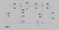
I've been working on a basic electronics review for future interview opportunities. Its about 400 questions long so I'm working through them. I've gotten to the section that I believe uses superposition to determine some measurements. The 1st question ask for Vac. The answer is 4.17V, but how to come up with that value is where I'm stuck. Ive done superposition for every source and have values for each Resistor. However, how to calculate from point A to C, I'm not seeing. I attached the circuit for the problem. V(10) = 3.33mA, V(5) = 1.66mA, V(15) = 5mA. From there I calculated voltage for each resistor in each source. V(10) -> point A = 3.33V, V(5) -> point A = GND, V(15) ->point A = 2.5V.

Thanks
 

Attachments

Thread Starter

LymanT

Joined Sep 25, 2014
24
Ok, taking the voltages for each source across the resistor in series with 10V leads me to this:

-2.5V+6.66V+1.66 = 5.82 -10V(source) = -4.18V


However adding the polarities from GND(pt C to pt A) up give me:

-1.66+10-6.66+2.5 = 4.18

??
 

MrAl

Joined Jun 17, 2014
11,389
Hi,

You have to be careful how you round in some of these problems if you want to match the textbook examples exactly.

The more exact result is:
vBA=25/6 volts

which is in decimal 4.1666666... (repeating decimal) which rounded to two decimal places is 4.17 volts.

If you round when you are doing the problem (sub steps) you may not get the exact result because that leads to different small differences.

Using superposition means "killing" all sources then "unkilling" one source at a time and taking the response(s) needed, then summing the results after all sources have been unkilled.

To kill a voltage source, you short it out. To unkill a source you remove the short but only for that one souce, and after you are done taking the response you then kill it again.
For this circuit that means that you calculate the voltage for both A and B as you kill each source, and then add up all three for A and all three for B. You can also subtract each time (B-A) and then add those results later.

Try that and see what you get.
 

WBahn

Joined Mar 31, 2012
29,978
Ok, taking the voltages for each source across the resistor in series with 10V leads me to this:

-2.5V+6.66V+1.66 = 5.82 -10V(source) = -4.18V


However adding the polarities from GND(pt C to pt A) up give me:

-1.66+10-6.66+2.5 = 4.18

??
I think your problem is that you are getting sloppy with the bookkeeping on your polarities. It's hard to follow what you are doing because you don't define your polarities in your posts -- which means that you probably aren't defining them for yourself, either.

First, define the current, I6, in the resistor of interest, R6, to be in one specific direction. Let's use upward. That means that

Vac = (V1) - (I6)(R6)

Since we are going to use superposition, we will be finding I6 as the superposition of currents do to the three independent sources:

I6 = I6_1 + I6_2 + I6_3

where the second subscript (the _n) is the subscript of the corresponding source.

Now we can look at the circuit by inspection to determine the polarities of these three currents:

I6_1 > 0
I6_2 > 0
I6_3 < 0

Any results that don't agree with these constraints we know is wrong (or our reasoning above is wrong) and there is no point going any further until that issue is resolved.

Now we can look at the circuits seen by each source in turn. The component values were chosen such that this can be done (with a bit of experience) by inspection as well.

I6_1 = 10 V / 3 kΩ = (10/3) mA
I6_2 = (1/2) (5 V / 3 kΩ) = (5/6) mA
I6_3 = -(1/2) (1/2) (15 V / 3 kΩ) = -(5/4) mA

These satisfy the expected polarities, so we can continue.

Vac = (10 V) - (2 kΩ)[( 10/3 + 5/6 - 5/4) mA]
Vac = (10 V) - [( 20/3 + 5/3 - 5/2) V]
Vac = (10 V) - [( 40/6 + 10/6 - 15/6) V]
Vac = (10 V) - [(35/6) V]
Vac = (10 V) - [(6 - (1/6)) V]
Vac = [4 + (1/6)] V
Vac = 4.17 V
 

Thread Starter

LymanT

Joined Sep 25, 2014
24
0302172030.jpg 0302172030.jpg 0302172030a.jpg 0302172030b.jpg You method looks easier.. I'm sure I messed up with my polarities. But I just assumed with conventional current flow.
 

Thread Starter

LymanT

Joined Sep 25, 2014
24
I6_1 = 10 V / 3 kΩ = (10/3) mA
I6_2 = (1/2) (5 V / 3 kΩ) = (5/6) mA
I6_3 = -(1/2) (1/2) (15 V / 3 kΩ) = -(5/4) mA
I'm curious as to what the 1/2 and -1/2 values are from?... It would seem easier to sum the currents, but are my current flows correct?
 

WBahn

Joined Mar 31, 2012
29,978
I'm curious as to what the 1/2 and -1/2 values are from?... It would seem easier to sum the currents, but are my current flows correct?
The factors of (1/2) are due to current division. The minus sign is because the current from V3 is going through R6 in the opposite direction of the direction that I defined I6 to be in.
 

Thread Starter

LymanT

Joined Sep 25, 2014
24
First, define the current, I6, in the resistor of interest, R6, to be in one specific direction. Let's use upward. That means that

Vac = (V1) - (I6)(R6)
By V3, are you referring to the 5V?

How do I define current for any specific load I am trying to solve for? When I did superposition for each source, I only defined them by the direction of conventional current flow. For instance, 10V : current flows upward, 5V : current flows upward, 15V : current flows downward.

You mentioned: 10V - I6(R6). Is any branch with a source always going to be the source minus the resisitor?

Last question, when measuring Vac, wouldn't it be (a) +I6(R6) - 10V = Vac? Polarities is where I am getting myself confused.

Thanks for the responses. This really helps
 

WBahn

Joined Mar 31, 2012
29,978
By V3, are you referring to the 5V?
Where did I say "V3"? I can't find what you are referring to. In your original schematic, V3 is the 15 V source. The 5 V source is designated V2.

How do I define current for any specific load I am trying to solve for? When I did superposition for each source, I only defined them by the direction of conventional current flow. For instance, 10V : current flows upward, 5V : current flows upward, 15V : current flows downward.
You can define it however you want -- you just then have to be consistent with whatever definition you use.

You mentioned: 10V - I6(R6). Is any branch with a source always going to be the source minus the resisitor?
The notion of "source minus the resistor" is nonsensical. In this case the voltage we are looking for is Vac = Va - Vc. Let's call the node between the 10 V source and R6 node 'm'. We can then write

Vac = Vam + Vmc

Vmc = V1 = 10 V

I6, because it is defined as the current flowing upward through R6, is going to be

I6 = (Vm - Va)/R6 = Vma/R6

This means that

Vma = I6·R6

But Vma = -Vam

So we have

Vac = -Vma + Vmc = -I6·R6 + 10 V = 10 V - I6·R6

[/QUOTE]
Last question, when measuring Vac, wouldn't it be (a) +I6(R6) - 10V = Vac? Polarities is where I am getting myself confused.
[/QUOTE]

By the rules applying to double subscript notation for voltage differences:

Vxy = Vx - Vy

Think of it like calculating the height differentials in a building.

Hxy = (Height of point X) - (Height of point Y)

If Hxy > 0, that means that point X is at a higher elevation than point Y

You calculation gives you the amount by which Vc is higher than Va, this is Vca, not Vac.
 

Thread Starter

LymanT

Joined Sep 25, 2014
24
It's all making sense now. I need to define my polarities with the 1st source I analyze. I got the rest of the questions correct after redrawing/redoing the problem. Looking through my book and playing with the circuit, could you lead me in the direction of how to calculate total power dissipated?. Would I have to calculate power for each component and sum? The last question on this problem threw me a curve ball.

P= VI
P= I^2(R)
P= V^2/R
 

Thread Starter

LymanT

Joined Sep 25, 2014
24
I may have figured it out....

I take the current of the resistor that is in series with the voltage sources, solve for power, then sum the power.

P(10) = 2.91mA(10V) = 29.1mW
P(5) = 830uA(5V) = 4.15mW
P(15) = -3.34mA(15V) = -50.1mW

P(total) = 29.1mW + 4.15mW + 50.1mW = 83.3mW

Please let me know if my reasoning is wrong.
 

WBahn

Joined Mar 31, 2012
29,978
If P(15) is negative (meaning that the source is absorbing power), why do you add it?

For any device, current leaving the positive terminal means that the device is delivering power. If current is entering the positive terminal, the device is absorbing power. Which is positive power and which is negative power is a matter of convention. There are two common versions of the passive sign convention. On states that the current is always defined so that it enters the positive terminal (as indicated by the defined polarity of the voltage across the device). this makes any device absorbing power have positive power and any device delivering power have negative power. A very common variant is to define the current as leaving the positive terminal for devices that are normally expected to supply power. This makes, under normal conditions, all devices have positive power. You can choose whichever makes the most sense to you, but you need to be sure that your convention is used consistently.

Also, be aware that you can't use superposition with power, because power is not linear. So you need to find the total current through the device and the total voltage across the device before calculating the power.
 

Thread Starter

LymanT

Joined Sep 25, 2014
24
I understand your logic. I thought that same thing. But the answer given is 83.4mW. So I figured they meant total power dissipated, not any one load.

"What is the total power dissipated?"

My reasoning for that way I calculated was the current going thru the resistor in series with a source is the same current going thru the source. Calculating the power at each source gave me the answer I posted. When summed together, it gave me the 83.4mW. Maybe I am wrong.

A video I came across stated that when negative power is calculated, it means the power is leaving the source, which I didn't quite understand. Your explanation is reverse that. I can calculate power for series and parallel circuits, but I've never done one for a multiple source circuit. So this type is new to me.
 

Thread Starter

LymanT

Joined Sep 25, 2014
24
So you need to find the total current through the device and the total voltage across the device before calculating the power.
I1 = 3.33mA
I2 = 1.67mA
I3 = 5mA

V1 = 10V
V2 = 5V
V3 = 15V

How to sum or subtract these values is unknown to me...Since V3 is the opposing current across some loads.
 

WBahn

Joined Mar 31, 2012
29,978
I1 = 3.33mA
I2 = 1.67mA
I3 = 5mA

V1 = 10V
V2 = 5V
V3 = 15V

How to sum or subtract these values is unknown to me...Since V3 is the opposing current across some loads.
Whether the currents due to the three sources all go in the same direction for a given load is irrelevant to this goal.

If you have a voltage source, V1, that has a terminal voltage of 10 V and the current leaving the positive terminal of that source is 3.33 mA, then that source is delivering 33.33 mW of power to the circuit it is connected to. Period. I don't need to know anything else about any other voltage or current in the circuit in order to tell you that.

However, is 3.33 mA the TOTAL current flowing out of the positive terminal of the 10 V source?

No. That is the current that is flowing in V1 that is attributable to the 10 V source. But there is also current flowing in it that is attributable to the other sources in the circuit. The power is due to the TOTAL current that is actually flowing.
 
Top