 Facebook
 Google
 GitHub
 Linkedin
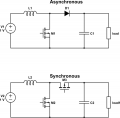
Hi I am looking for a solution that allows me to control the speed of a DC motor using the output from a boost converter as seen in the attached image.
My input it 5v and I want to be able to adjust the speed of the motor by bringing it from a stall (less than 2v) to 13v, I would like to incorporate an H bridge for the occasional reverse but a DPDT switch would be fine.
A simple inverting buck boost works for my design but my goal is efficiency, I suspect that using a synchronous boost converter paired with a PWM to set the average voltage to the motor would be most efficient but I am having trouble understanding the no load condition during the OFF state of the PWM signal without a feedback network and if it is even necessary.. I can't seem to find any algebra that relates effects and losses in a converter that is being switched from a load to no load condition.
Thanks
Attachments
-
 15.2 KB Views: 6


