Facebook
 Google
 GitHub
 Linkedin
I have two Danfoss RDS 20 dc motor control boards. Don't have circuit diagrams for them. The boards are double sided, difficult to trace. What i found so far:
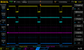
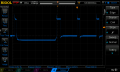
They use 555 timer as oscillator to drive SCR rectifier. Duty cycle is controlled with a 5K pot through 324 opamps. On one board there's 12V supply on the timer and nothing else. The other is stuck on 12% duty cycle and the pot doesn't affect it. What i can't figure out is the circuit for 555 they use. It doesn't look like anything from datasheet's possible applications. Maybe someone can explain to me how they regulate duty cycle of 555 based on my measurements (see attached). Also Vpp might be a little off, was measuring with a cheap pocket scope.
They use 555 timer as oscillator to drive SCR rectifier. Duty cycle is controlled with a 5K pot through 324 opamps. On one board there's 12V supply on the timer and nothing else. The other is stuck on 12% duty cycle and the pot doesn't affect it. What i can't figure out is the circuit for 555 they use. It doesn't look like anything from datasheet's possible applications. Maybe someone can explain to me how they regulate duty cycle of 555 based on my measurements (see attached). Also Vpp might be a little off, was measuring with a cheap pocket scope.
Attachments
-
 330.4 KB Views: 9