 Facebook
 Google
 GitHub
 Linkedin
Hello there!
Ok: In a school project I want to controll a light dimmer. The old dimmer needs a 0-10V signal to controll the lights. I have a Arduino Uno, but as probably known, the Arduino only have a system voltage of 5V. So I need to double the PWM Output signals from the board.
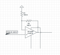
For this purpose I design a small circuit with an OP-AMP. But to Output a 10V signal, I also need a 10V supply Voltage. On the attached File, you can see the basic circuit. The two lower cables needs to be supplied by the 10V and a 0V Voltage. The right cable is the Output.
So my question is: what is the best way to supply the 2 supply Voltages?
I had 2 basic ideas:
Ok: In a school project I want to controll a light dimmer. The old dimmer needs a 0-10V signal to controll the lights. I have a Arduino Uno, but as probably known, the Arduino only have a system voltage of 5V. So I need to double the PWM Output signals from the board.
For this purpose I design a small circuit with an OP-AMP. But to Output a 10V signal, I also need a 10V supply Voltage. On the attached File, you can see the basic circuit. The two lower cables needs to be supplied by the 10V and a 0V Voltage. The right cable is the Output.
So my question is: what is the best way to supply the 2 supply Voltages?
I had 2 basic ideas:
- The whole construct is supposed to be only powered by a USB-Port. But if I have to, I could power it by in an external powersupply with goes into a socket.
- I take the 5V output from the Arduino and double it once using a method without Op-amps. Something like: convert the 5V to an AC signal and then double the Signal by an AC-DC Voltage Doubler like this
Attachments
-
 17.5 KB Views: 127


")


