Computing the efficiency in LTspice

Papabravo

Joined Feb 24, 2006
22,058
I don't think using a voltage source as a load is a valid way to do things. At least I've never seen anybody else do this.
 

Papabravo

Joined Feb 24, 2006
22,058
Consider V2 to be load regulated with some circuitry maintaining constant voltage on it.
Or the battery.
I'm not convinced that you can make a load from a voltage source. I'd be more convinced if you used a current source as an "active load". At least I have seen that done before. It also makes no sense that you get a higher efficiency with a higher voltage. Can you make it to 100%? If you can then the method is certainly bogus.
 

WBahn

Joined Mar 31, 2012
32,706
I haven't reviewed the circuit or the calculations, but getting higher efficiency with higher voltage makes some sense. As the load's voltage source gets higher, less and less current is sent to it. Eventually, it would be high enough to keep D3 reverse biased so that no current was delivered to it. At the same time, D1 and C1 would act as a peak detector and no current would flow in it. At the extreme, you would have an indeterminate efficiency (0/0), but the simulator might well see that as approaching 100% efficiency, albeit that is useless efficiency since power is not being delivered or consumed.
 

Papabravo

Joined Feb 24, 2006
22,058
I don't see how. What will the current in R1 be under those conditions?
I'm just looking at the trend in the calculations he is making. I think having a voltage source as a load is a questionable proposition and I'm not sure if the purported calculation of efficiency means anything or not. As the V2 voltage rises above the peak of the sine wave I can't see how any power transfer would be possible. The TS can run that experiment if it pleases him. I'll await the results.
 

WBahn

Joined Mar 31, 2012
32,706
I'm just looking at the trend in the calculations he is making
Notice that the trend is not increasing without bound -- it is going asymptotic to 100%. There's nothing there that indicates it would ever exceed 100%.

I think having a voltage source as a load is a questionable proposition and I'm not sure if the purported calculation of efficiency means anything or not.
How would you calculate the efficiency of a battery charger? Why wouldn't the ratio of average power delivered to the battery divided by the average power delivered by the charger be reasonable? As long as the times over which the averages are taken coincide, this is the same as the ratio of energy delivered to the battery divided by energy delivered produced by the source.

As the V2 voltage rises above the peak of the sine wave I can't see how any power transfer would be possible.
It wouldn't be -- which is not a problem. 100% of zero is zero. You would also see the efficiency drop to zero as long as the source is supply any power to anything other than the load source.
 

Thread Starter

Michal Podmanický

Joined May 11, 2019
289
Of course at high V2 voltages (like >400V) the efficiency starts to decrease rapidly.
I don’t want to use this circuit for V2 >200V.
At low V2 voltages the diode drops have a huge impact on lowering efficiency.
The small 0.1 resistor has almost no impact no efficiency at whatever V2 level.
All waist seems to be related to current, so higher V2 -> lower current -> lower waists.
 

MrAl

Joined Jun 17, 2014
13,667
Hi,
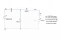
I’d like to compute the efficiency of attached circuit for V2 range 20-300V.
Can you please check if the formulas are correct?
View attachment 328169
Results:
View attachment 328170
Hi

I do not have any problem at all with a voltage source as a load we do that all the time with battery chargers, but what is up with that image. Yikes, looks like it went through the sawmill :)

Anyway, you seem to have the right idea about calculating efficiency. I could check it on another simulator if you like.
If you do not really have a voltage source as output, then you have to check to make sure that it only absorbs power and never delivers any. This seems to be the case because of that diode though.

Here is the image cleaned up a little. Note the bytes count on the original vs this new image as well as the dimensions. The original takes up 5MB while the cleaned-up version takes just 74kB which is just 1.5 percent of the original byte count.
 

Attachments

Thread Starter

Michal Podmanický

Joined May 11, 2019
289
Thx MrAI.

I would be glad if I could compare the results from some another simulator or approach.
It’s important for me to be ~100% sure I’m not wrong since load circuit has to be designed according this results, another words at what voltage should I maintain the V2 to design be efficient.
V2 is resonant SMPS in my case btw, not a battery.
I’d like to find out where is the origin of losses in this doubler at different V2 levels.
 
Last edited:

MrAl

Joined Jun 17, 2014
13,667
Thx MrAI.

I would be glad if I could compare the results from some another simulator or approach.
It’s important for me to be ~100% sure I’m not wrong since load circuit has to be designed according this results, another words at what voltage should I maintain the V2 to design be efficient.
V2 is resonant SMPS in my case btw, not a battery.
I’d like to find out where is the origin of losses in this doubler at different V2 levels.
Hi,

Taking another quick look, it appears that the only energy dissipators are the resistor and two diodes. The rest should go from the input right to the output. This means that the efficiency will be related to the output voltage as some ratio of the power in the two diodes plus the power in the resistor, to the power in the output load.
That's if the resistor is NOT part of the load. If the resistor is part of the load, then you have to take the voltage from across the resistor and the output load.
Assuming the resistor is not part of the load and we dissipate (say) 1/2 watt in each diode and 1 watt in the resistor for some output load voltage, that would mean 2 watts wasted. If the output current was 1 amp and the voltage 200 volts DC, that would be a small fraction of the total power:
2/200=0.01 which is just 1 percent lost as heat.
As the voltage comes down though, with everything else the same it would be around:
2/20=0.1 which is 10 percent lost as heat.

There is the question of how efficient the capacitor is too though. You'd have to look into that. Caps are not 100 percent efficient at storing and releasing energy. The cap also has to be of decent quality.

For something this important you really must do a bench test prototype there's absolutely no way around that. No power product on earth is made without a bench test followed by a life test. The minimum life test would be to run overnight at full power or whatever it will be normally run at.

This can be analyzed without doing a simulation but of course that takes more time.
This might also be viewed as a transformerless power supply.

Oh, so is that resistor part of the load or not?
 
Top