 Facebook
 Google
 GitHub
 Linkedin
Hi guys,
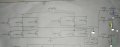
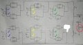
I am fixing an inverter welding machine. The schematics show the high power circuit: the H-bridge and the output rectifier. You can identify which coil belongs to which transformer by seeing my color markings of both schematics.
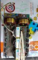
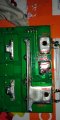
The pictures are the output rectifier. Important points are the positive and negative outputs: O/P(+) and O/P(-), which we connect them across metal pieces we want to weld them together. Also, there is the ground (which I define that node myself).
It looks almost like the ground and the O/P(-) are tied together by the "unknown plate". However, if we look at the bottom of the PCB, there are two traces (marked orange and purple). One of them connects to the O/P(-) and the other to ground. The voltage at O/P(-) with respect to ground will be fed back to the PWM controller board. The ground is connected to that of the PWM controller board.
So, I would like to ask what is the function of this "unknown plate". What is the point of feeding this voltage back to the controller?
Sincerely,
BlackMelon
I am fixing an inverter welding machine. The schematics show the high power circuit: the H-bridge and the output rectifier. You can identify which coil belongs to which transformer by seeing my color markings of both schematics.
The pictures are the output rectifier. Important points are the positive and negative outputs: O/P(+) and O/P(-), which we connect them across metal pieces we want to weld them together. Also, there is the ground (which I define that node myself).
It looks almost like the ground and the O/P(-) are tied together by the "unknown plate". However, if we look at the bottom of the PCB, there are two traces (marked orange and purple). One of them connects to the O/P(-) and the other to ground. The voltage at O/P(-) with respect to ground will be fed back to the PWM controller board. The ground is connected to that of the PWM controller board.
So, I would like to ask what is the function of this "unknown plate". What is the point of feeding this voltage back to the controller?
Sincerely,
BlackMelon
Attachments
-
 2.2 MB Views: 6
 -
 1.7 MB Views: 6
 -
 2.1 MB Views: 6
 -
 1.3 MB Views: 5
 -
 1.3 MB Views: 4


