DC-DC Buck Boost Converter Power Losses

Papabravo

Joined Feb 24, 2006
22,084
You mean you want more details about my design or you don't understand how to do it?
I mean anybody can throw symbols onto a schematic diagram without important details and say: "here, this is an exercise for the reader". I don't have the time or the patience to figure out what your intention might be. You design it and I'll evaluate it. That is the way this site works. I'm retired and no longer getting paid big bucks to do design work any more.
 

crutschow

Joined Mar 14, 2008
38,574
I want a PWM in LTspice, How can i get it?
Generate a triangle-wave with the pulse option using a voltage source.
Apply that triangle-wave to one input of a comparator.
Apply the variable control signal to the other comparator input.
The comparator output is a PWM signal with duty-cycle proportional to the value of the control signal.
 

Thread Starter

fadh9l

Joined Oct 1, 2016
31
Generate a triangle-wave with the pulse option using a voltage source.
Apply that triangle-wave to one input of a comparator.
Apply the variable control signal to the other comparator input.
The comparator output is a PWM signal with duty-cycle proportional to the value of the control signal.
Is there is any problem if i send you my design and you make a PWM? because i do not got it how to do it.
 

ronv

Joined Nov 12, 2008
3,770
Go to the Linear web site and look at the LTC3114-1 circuit.
Then go to LtSpice and duplicate that circuit. You can find the IC under power products.
The frequency will be much higher, but that should be okay.
 

Thread Starter

fadh9l

Joined Oct 1, 2016
31
Go to the Linear web site and look at the LTC3114-1 circuit.
Then go to LtSpice and duplicate that circuit. You can find the IC under power products.
The frequency will be much higher, but that should be okay.
Brother, i already have designed my buck-boost but i can not control it, because i do not know how design the control stage properly.
 

MrAl

Joined Jun 17, 2014
13,726
Brother, i already have designed my buck-boost but i can not control it, because i do not know how design the control stage properly.
Hi there,

You should show your circuit schematic, hopefully a clear drawing that we can see well, then i think people will be able to help with this project. Since you said you already have a design in the works, it would be good to see it as it is so far and then maybe add or modify it to get it working.
 

Thread Starter

fadh9l

Joined Oct 1, 2016
31
Hi there,

You should show your circuit schematic, hopefully a clear drawing that we can see well, then i think people will be able to help with this project. Since you said you already have a design in the works, it would be good to see it as it is so far and then maybe add or modify it to get it working.
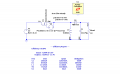
This is my buck-boost converter with a current mode controller. I want a current mode controller. I want my output current to be constant at 0.404 A. If you have another way (controller circuit) to control the output current Plz give it to me.
 

Attachments

MrAl

Joined Jun 17, 2014
13,726
This is my buck-boost converter with a current mode controller. I want a current mode controller. I want my output current to be constant at 0.404 A. If you have another way (controller circuit) to control the output current Plz give it to me.
Hi,

Well i can tell you right off that the modern way to do this is to use a chip made for this purpose and then just follow the manufacturers recommendations. That means less work for you. Depending on frequency, you may need a MOSFET driver chip too.

I am not sure i understand your circuit. It looks like you have an integrator combined with a ramping PWM producing comparator, but the input to the integrator comes from the 15 volts supply! What are you intending here?
 

Thread Starter

fadh9l

Joined Oct 1, 2016
31
Hi,

Well i can tell you right off that the modern way to do this is to use a chip made for this purpose and then just follow the manufacturers recommendations. That means less work for you. Depending on frequency, you may need a MOSFET driver chip too.

I am not sure i understand your circuit. It looks like you have an integrator combined with a ramping PWM producing comparator, but the input to the integrator comes from the 15 volts supply! What are you intending here?
Can you send me the chip name (IC) that can make the output current constant (current mode controller) and how can i connected to my buck-boost converter.
 

MrAl

Joined Jun 17, 2014
13,726
Can you send me the chip name (IC) that can make the output current constant (current mode controller) and how can i connected to my buck-boost converter.
Hello again,

Did you try the TI site? They have an app note snva555.pdf that talks about current mode control.
I would suspect that the implementation is going to be by design where you pick a buck/boost chip and then go from there by implementing current mode control.

A question that does come up is how accurate does the control have to be, and is this for an LED driver?
 

Thread Starter

fadh9l

Joined Oct 1, 2016
31
Hello again,

Did you try the TI site? They have an app note snva555.pdf that talks about current mode control.
I would suspect that the implementation is going to be by design where you pick a buck/boost chip and then go from there by implementing current mode control.

A question that does come up is how accurate does the control have to be, and is this for an LED driver?
Is there any other way that i can design a current mode controller for my buck-boost because i am really stuck in this issue?
 
Top