Dark sensor circuit using LM393 question.... unstable OFF/ON... flickering

eetech00

Joined Jun 8, 2013
4,709
Question:
My 5mm LEDs are pre wired with leads and a current limiting resistor. They are rated for 12v. I'm guessing that 2.2k resistor is not necessary? It also appears that I have some mismatched designations. I will fix them and repost. Sorry for the confusion.

FIXED SCHEMATIC AND PCB ARE ATTACHED
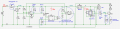
The maximum ATiny GPIO output current is 40mA before subject to damage, but it is not limited, and you really want to limit the current to somewhat less (Typically 50-70%). Since the transistor base only needs about 2-3ma to drive the LED's, the 2.2k base resistor limits the current to about 2mA. So I recommend leaving the resistor in or there is a risk of damage. The 22k is a pull-down to ensure it is turns off when not active.

Regarding the RVP mosfet.
The Si2305 mosfet VDS/VGS is not rated for this purpose. It will eventually become damaged.
The Zener and resistor I added keeps the gate voltage below spec but does nothing for the VDS requirement.
Choose a mosfet with a minimum 20v VDS and low RDSon.

Last point-
The open Atiny inputs can probably be used as an voltage comparator to monitor the LDR. Then you can probably completely remove the LM393.
 

Thread Starter

johnaustinkaty

Joined Jul 16, 2021
284
eetech00,
Thx for the additional guidance, recommendations and instructions. Understood and much appreciated. I'll address these points tomorrow.
-John
 

Thread Starter

johnaustinkaty

Joined Jul 16, 2021
284
Last point-
The open Atiny inputs can probably be used as an voltage comparator to monitor the LDR. Then you can probably completely remove the LM393.
I may eventually use the lm393 to provide battery status results that will trigger a message on an ESP32 to be sent to a phone via wifi. That function has already been tested and works very well through the app I have created.
Regarding the RVP mosfet:
You are absolutely right. I did have one RVP mosfet burn up, but thought it was a one off freak event. I was obviously wrong.
Any suggestions for the appropriate RVP mosfet to replace the current one? LCSC part#?
 

LesJones

Joined Jan 8, 2017
4,509
You do not have a current limiting resistor in series with the 2 LEDs marked RA. This is needed unless these LEDs have built in current limiting resistors.

Les.
 

ericgibbs

Joined Jan 29, 2010
21,463
Hi john,
On your latest circuit, I don't see any power rail smoothing/decoupling capacitors for any of the power rails.
The existing100nF caps require parallel higher value uF capacitors, say 100uf/220uF

Also, what is the 12V main power source?
If the 12V rail is not stable, the LM393 inputs will also not be stable.

It would be helpful if you posted a description on how the project is supposed to operate when installed.
E
 
Last edited:

Thread Starter

johnaustinkaty

Joined Jul 16, 2021
284
You do not have a current limiting resistor in series with the 2 LEDs marked RA. This is needed unless these LEDs have built in current limiting resistors.

Les.
They do have resistors, but the LEDs are in parallel currently. An earlier post stated that these two LEDs needed to be in series if controlled by PWM, which they are.....for now, and that they could not both have resistors.
 

Thread Starter

johnaustinkaty

Joined Jul 16, 2021
284
Hi john,
On your latest circuit, I don't see any power rail smoothing/decoupling capacitors for any of the power rails.
The existing100nF caps require parallel higher value uF capacitors, say 100uf/220uF

Also, what is the 12V main power source?
If the 12V rail is not stable, the LM393 inputs will also not be stable.

It would be helpful if you posted a description on how the project is supposed to operate when installed.
E
The power source is a standard 12v 7Ah feeder battery. The voltage will typically fluctuate between 13+v and 11.5+v. The unit works just fine down to 10v. The unit is energized at dusk utilizing an LDR, the LM393 resistors and IRFZ mosfet. The RA LEDs (5mm having leads with built in resistors) come on at 50% brightness. The high power LED comes on at 1% brightness.... very dim. When motion is sensed, the RA (red alert) LEDs blink 5 times at full brightness. Then the high power LED begins brightening to 93% brightness over a 90 second period, holds there for two minutes, then slowly fade back down over a 45 second time period. This cycle repeats each time motion is sensed. This light will typically be mounted in remote areas. A 10 watt solar panel and controller recharge the battery during daylight hours.
 

eetech00

Joined Jun 8, 2013
4,709
They do have resistors, but the LEDs are in parallel currently. An earlier post stated that these two LEDs needed to be in series if controlled by PWM, which they are.....for now, and that they could not both have resistors.
Regarding the two LEDs driven by 12v PWM.
If you connect them in parallel, each LED will need a dedicated limiting resistor, and a dedicated current will flow in each. The total required drive current will be the sum of both LED "strings". If you connect the LED(s) in series, creating a single LED "string", then they'll need a single current limiter resistor, and the total required drive current will flow in both, requiring basically half the total current than if connected in parallel. If more info is needed, search the internet for "LED series vs parallel".
 

Thread Starter

johnaustinkaty

Joined Jul 16, 2021
284
Regarding the two LEDs driven by 12v PWM.
If you connect them in parallel, each LED will need a dedicated limiting resistor, and a dedicated current will flow in each. The total required drive current will be the sum of both LED "strings". If you connect the LED(s) in series, creating a single LED "string", then they'll need a single current limiter resistor, and the total required drive current will flow in both, requiring basically half the total current than if connected in parallel. If more info is needed, search the internet for "LED series vs parallel".
Great point. I understand. I want to use the supply of these LEDs that I have on hand and will switch to series at that time and use only one resistor for the 20 mA current.
 

Thread Starter

johnaustinkaty

Joined Jul 16, 2021
284
Hi john,
On your latest circuit, I don't see any power rail smoothing/decoupling capacitors for any of the power rails.
The existing100nF caps require parallel higher value uF capacitors, say 100uf/220uF

Also, what is the 12V main power source?
If the 12V rail is not stable, the LM393 inputs will also not be stable.

It would be helpful if you posted a description on how the project is supposed to operate when installed.
E
If these caps are required, where would they go specifically?
 

ericgibbs

Joined Jan 29, 2010
21,463
hi ,
The IRLM2502 is an N MOSFET, how would you connect it for reverse supply protection?
E

Update:

What is the current load for the project, also the power LED current?
 

Thread Starter

johnaustinkaty

Joined Jul 16, 2021
284
hi ,
The IRLM2502 is an N MOSFET, how would you connect it for reverse supply protection?
E

Update:
What is the current load for the project, also the power LED current?
Can you suggest the proper P mosfet. I will look in LCSC to see what I can find.
EDITED:
The max current load is approx .550 A (green LED).
The max current to the super bright 3up LED (green) is around .510 A. The red LED takes around .410 A.
 
Last edited:
Top