Facebook
 Google
 GitHub
 Linkedin

Hi,
I am designing a linear CV/CC source driver, mainly for testing lab fabricated LEDs with varying forward voltages from ~1V up to 9V and forward currents up to 100mA. The LED is modelled with various parasitics in good hope of simulating a wide range of possible samples.
The driver consists of a PNP current mirror that drives a NPN, which in turn regulates the voltage and current through the LED via two op-amps in negative feedback - one for voltage and one for current. The op-amp currently in control (CC or CV) sinks the current away from the base of the NPN and caps the LED at the value, set by the 3.3V DAC.
The schematic is shown in the picture below:
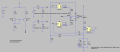
For current sensing I used the INA293A3 with 50V/V gain, so that a 100mA current across its 0.5ohm sense resistor results in a 2.5V output. The divider on the voltage sense side is for scaling the LED voltage range down to the DAC voltage range. C1, C4, R11 and R12 are forming two integrators that I used to compensate the two op-amps to prevent them from oscillating. R13 is the emitter degradation resistor to help stabilize NPNs gain. The RC filters at the DAC output (voltage source) are meant to damped the voltage steps.
I have ran several simulation scenarios, from setting DC operating points to simulating PWM and of course checking for a smooth CC->CV and CV->CC handover. This is where the problem arose. The LED simulated here has a forward voltage of 1.2V. In this particular scenario, the voltage is set first (0.75V at 0.3ms after simulation start), while the current is set to 0, keeping the LED off as intented. Then, at 1.5ms, current is set to 50mA, putting the LED into CC mode. A short pulsed, few us long current spike occurs up to 14mA as the current then settles down to 6mA. Then, at 4ms, the voltage is set to 3.75V while the current setting remains the same, putting the LED into CV mode. Current spikes again, reaching a peak value of 120mA, before settling down to 50mA.
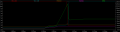
It appears to me that when the voltage is set to 3.75V, the LED voltage begins to rise accordingly. It then crosses its forward voltage (1.2V) point, after which current begins to rise exponentially, while the LED voltage rises only a very slowly. Because of the integrator in the CC circuit side, the op-amp fails to start sinking the current in time, causing current to rise beyond the 50mA set point.
I am puzzled on how to prevent this from happening in terms of securing a fast response from the CC loop while maintaining stability. Any help would be much appreciated.
Thank you in advance!
I am designing a linear CV/CC source driver, mainly for testing lab fabricated LEDs with varying forward voltages from ~1V up to 9V and forward currents up to 100mA. The LED is modelled with various parasitics in good hope of simulating a wide range of possible samples.
The driver consists of a PNP current mirror that drives a NPN, which in turn regulates the voltage and current through the LED via two op-amps in negative feedback - one for voltage and one for current. The op-amp currently in control (CC or CV) sinks the current away from the base of the NPN and caps the LED at the value, set by the 3.3V DAC.
The schematic is shown in the picture below:
For current sensing I used the INA293A3 with 50V/V gain, so that a 100mA current across its 0.5ohm sense resistor results in a 2.5V output. The divider on the voltage sense side is for scaling the LED voltage range down to the DAC voltage range. C1, C4, R11 and R12 are forming two integrators that I used to compensate the two op-amps to prevent them from oscillating. R13 is the emitter degradation resistor to help stabilize NPNs gain. The RC filters at the DAC output (voltage source) are meant to damped the voltage steps.
I have ran several simulation scenarios, from setting DC operating points to simulating PWM and of course checking for a smooth CC->CV and CV->CC handover. This is where the problem arose. The LED simulated here has a forward voltage of 1.2V. In this particular scenario, the voltage is set first (0.75V at 0.3ms after simulation start), while the current is set to 0, keeping the LED off as intented. Then, at 1.5ms, current is set to 50mA, putting the LED into CC mode. A short pulsed, few us long current spike occurs up to 14mA as the current then settles down to 6mA. Then, at 4ms, the voltage is set to 3.75V while the current setting remains the same, putting the LED into CV mode. Current spikes again, reaching a peak value of 120mA, before settling down to 50mA.
It appears to me that when the voltage is set to 3.75V, the LED voltage begins to rise accordingly. It then crosses its forward voltage (1.2V) point, after which current begins to rise exponentially, while the LED voltage rises only a very slowly. Because of the integrator in the CC circuit side, the op-amp fails to start sinking the current in time, causing current to rise beyond the 50mA set point.
I am puzzled on how to prevent this from happening in terms of securing a fast response from the CC loop while maintaining stability. Any help would be much appreciated.
Thank you in advance!
Attachments
-
5.5 KB Views: 1