 Facebook
 Google
 GitHub
 Linkedin
Hello
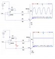
I created op amp MOSFET current source. It had oscillations as per picture, so RC circuit was was added and problem was resolved. What I am wondering is a transfer function of it and how to treat it. Controller works as an error amplifier, but is it the simplest form of proportional controller? And after addition of the capacitor, does it make this circuit simple PI controller? If so how can I write transfer function of it. For example if I Op Amp is PI controller Gc(B) what the Kp gain will be? And I dont know how to describe transfer function of Mosfet Gp(B).
Could someone please help me with this.
Attachments
-
 122.6 KB Views: 38
 -
 10 KB Views: 31


