Current source sum behaving unexpectedly

Thread Starter

jacopo1919

Joined Apr 12, 2020
113
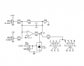
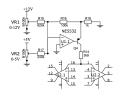
what i need is 0 to 2mA of current out of this current source.
I 
breadboarded this and it works fine when one of the 2 voltage are fed one at the time; both (0 to 12V and 0 to 5V) give me the desired 2mA.

(the OTA used is a LM13700 and the Amp bias input is 2 diodes from the negative rail)


Strange things happen when i sum them.

if i slowly increase and sum the 2 currents, the measured sum at the output first reaches 2mA, but just after that it starts to decrease untill it reaches 1.6mA when the 2 currents are at the maximum.


i was expecting them to be linearly summed and being limited by R14.


i don’t understand why this occurs
 

Attachments

AlbertHall

Joined Jun 4, 2014
12,345
I think it is because Q4 is saturating. Try reducing the value of R14. As this is a constant current source its value will not affect the current, only the collector voltage of Q4.
 

Thread Starter

jacopo1919

Joined Apr 12, 2020
113
if i reduce R14, then the problem doesn't occur but in that case i will exceed 2mA at the sum.
It is mandatory to keep the current under that value or i fry the OTA.
 

AlbertHall

Joined Jun 4, 2014
12,345
So what you want is that as the input is increased the current should increase up to 2mA, but further increases in input should leave the current at 2mA?

Does it matter exactly what input is required to get the 2mA?
 

Thread Starter

jacopo1919

Joined Apr 12, 2020
113
Exactly.
One input has to be 0 to 5V because will be an external signal, the other one could vary. I chosed a pot +12V to ground because was looking like the easiest way
 

Ian0

Joined Aug 7, 2020
9,677
Has the output gone unstable? Does a capacitor across R16, or a resistor between the NE5532 - input and ground fix it?
 

Thread Starter

jacopo1919

Joined Apr 12, 2020
113
the output is stable.
It just decrease at some point. I tried a 5n6 capacitor across r16 and a 620R from non inv input to ground but the behaviour remains the same.
i have uploaded a short video.
First i tweak the 0 to 5v pot, then the 0 to 12V pot, then i sum them togheter and you can see that after 2mA it goes back to 1.6mA.
i recorded horizontally, excuse me, didn't want to give you a stiff neck.

 
Last edited:

AlbertHall

Joined Jun 4, 2014
12,345
I think this will work. Connect the circuit below between the base of Q4 and the +12V and add a 2.2k resistor between the base of Q4 and U1.1 output.
Make R2 a 100Ω pot and R2 470Ω. Set the pot so the limit is 2mA.
1645349186580.png
 

Ian0

Joined Aug 7, 2020
9,677
R14 is too large.
At maximum the inputs currents are 12V/620k + 5V/240k = 40uA.
40uA across 100k = 4V
So the output current is 4V/1k = 4mA
4mA through 3.9k is 15.6V - you have run out of headroom.
With a negative supply of 12V, less 1.3V for the diodes on the LM13700 current input, less 4V across the 1k resistor, less a volt or so for the transistor leaves 5.7V. If you want 4mA into the LM13700 (which you shouldn't as it is specified as 2mA maximum) then R14 must be smaller than 5.7V/4mA = 1.4k
 

Thread Starter

jacopo1919

Joined Apr 12, 2020
113
@AlbertHall Do you mean like in the picture attached (AAC1)?

@Ian0 I need maximum current at the current source output to be 2mA. (Because as you mentioned, tha't the max Ibias specified for LM13700).

Each input should individually generate 2mA out of Q4, but when 2 signals are summed toghether, the limit still has to be 2ma.

What i was expecting is actually to run out of headroom when the 2 signals are at their maximum, .. but i thought that the current would stop at 2mA once reached that point. Instead of this behaviour, is coming back to 1.6mA as shown in the video.

Your comment made me think that a simple 2V zener diode will limit the current at 2V/1k = 2mA. I drew it up, (AAC2) now i will try on breadboard
 

Attachments

Thread Starter

jacopo1919

Joined Apr 12, 2020
113
Use a 2.048V reference diode across the 100k resistor.
this actually does solve the issue! i placed a 2.2V ( those extra 0.2V are probably dued to VCE) zener diode across R14.
Thanks.
I still don't understand why it was behaving like that though. Mistery
 

Ian0

Joined Aug 7, 2020
9,677
this actually does solve the issue! i placed a 2.2V ( those extra 0.2V are probably dued to VCE) zener diode across R14.
Thanks.
I still don't understand why it was behaving like that though. Mistery
As the op-amp output voltage gets more negative, the current in R18 keeps increasing. That current can't be supplied through R14, so it goes from the op-amp output through the transistor base. The collector cannot be more positive than the emitter, so the voltage across R14 starts to decrease - and that is exactly what you observed.
 
Top