Facebook
 Google
 GitHub
 Linkedin
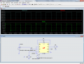
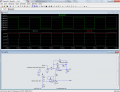
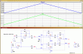
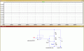
Well, here is one way.The input is 2.46V relative to GRND at both IN's when I do not measure any current with the probe and when I do measure 1 amp.the IN- is 1mV higher (2.47V) and IN+ 2.46 V
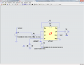
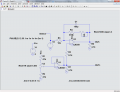
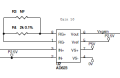
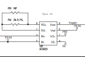
I think you need a +/- supply. At least that is the only way I can get it to work.
Then you need an offset adjust to put the other input at the same level as the sensor output otherwise the gain saturates it..
Ref to ground.
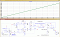
Edit: A schematic would help.