Hi
Are you trying to test the injectors for 'wear, sticky or dirty'?
I guess you know that spike on the waveform is due to the back emf produced by the injector coil inductance, when the driving current is switched off.?
Indeed, if the little pintle hub (the black arrow in one of previous posts) in the back emf dissapears this means that the injector is stuck (needle doesnt move).
See: no pintle hub in post below (defective injector):
Hi
I have just built the original circuit I posted earlier, it works fine for a Hall input range of +/-10mV [ superimposed on a +2.5v DC level, the Hall Q point]
For dirt or wear I think you need to check the spray pattern and the average volume of fuel over X injections with Y injection duration, X and Y varying for each injector type.
Would you add a protection circuit considering that with bad sparkplugs or other HV wire interruptions the spark could go to the pick up probe?
I thought of CNY65x or CNY66x serie? Are those suited for analog signals as the HV pick up probe circuit and the 10:1 probe following it?
Or is it better to use a isolated ampli as http://uk.farnell.com/webapp/wcs/st...tegoryId=700000021004&langId=44&storeId=10151
hi,
I would not use a isolated OPA for connecting the HV probe, you are not interested in the actual wave shape of the sync pulse.
A resistor/diode clamp network would be sufficient IMO.
There are simple circuits on the web for ignition pick off
E
A last question for anyone who follows the tread. After sim with LT spice, whats the easiest way to design the PCB?
Many thanks for your advise and suggestions in this tread !!!!
I only will be able to make the complete circuit in june or july and 'll keep you updated.
hi,
I would not use a isolated OPA for connecting the HV probe, you are not interested in the actual wave shape of the sync pulse.
A resistor/diode clamp network would be sufficient IMO.
There are simple circuits on the web for ignition pick off
E
In fact the main purpose of my question regarding insulation of the input circuits is to protect the Bitscope and PC from sparks firing to the P.U.probe. This made me think of a comparable situation of defibrillators in combination with ECG's.
Searching the net I found a chip protecting the ECG (differential ampli 0.5 mV sensitivity) from defibrillator (up to 5KV).
I see designers use neon: https://www.maximintegrated.com/en/app-notes/index.mvp/id/5724
And is somebody having experience with this: https://datasheets.maximintegrated.com/en/ds/MAX13202E-MAX13208E.pdf
Anyone used those in combination with classic input protection circuits?
hi,
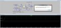
I would consider a basic limiter/diode clamp circuit as per this image.
I appreciate the waveforms are idealised, but it should be sufficient for syncing a scope trace.
Hi eric, have downloaded LTspice and did a first try with yr diagram and a few things more : the pickup probe; the neon, input impedance of scope.
I also tried to simulate the firing goiing directly to the pickup probe itself instead of the spark plug (right half) . I would like to add a few zeners and find the right specifications for all components. Strange that the difference between the 2 diagrams results only in doubling the output. Looks safe for the Bitscope and PC... as long as it behaves well...
hi patpin,
The problem with the direct connection to the spark plug, will be the break over voltage of the 1meg to 0v will be exceeded.
You could use a series of resistors to for the 1meg in order to avoid the over voltage on a single resistor.
I would avoid a direct connection.
Note: in your your sim circuits all the Caps have values of Farads!!!!
Use the C suffix of p, n or u to indicate pico, nano or micro.
Hello Eric,
I do not know if sending this net list is possible on AAC and if it is not too much asked to you. I would like to combine it with the HV protection diagram of the other tread in other to check out n the Vg solution voor de clamp probe. Thanks for all input !!
 Facebook
 Google
 GitHub
 Linkedin