Current & Power Gain For A Two-Stage CE Amp

Thread Starter

aac044210

Joined Nov 19, 2019
178
You cannot include RL resistance in the equation because Zout is a resistance seen by RL (resistance seen from Zout into the the amplifier output).

To find the Zout after you apply negative feedback the voltage feedback in series with the input ( voltage-series feedback).
You need to find the loop gain.

We can use an approximate method to find the loop gain:

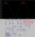
We first need to find the open-loop gain AOL using this circuit:
View attachment 195524


For Ic1 = Ic2 ≈ 1mA and β = 280... we have: re1 = re2 = 26Ω hence:

AOL ≈ (Rc1||RB21||RB22||(β * re2))/(re1+RF1) * (Rc2||RL||(RF1a+RF2a))/re2 = 8.6 V/V * 82V/V ≈ 705 V/V

And the loop gain is loop gain ≈ (705 V/V *(47Ω/8.77kΩ)) ≈ 3.8


Therefore Zout ≈ (Rc2||(RF1a+RF2a))/(1 + loop gain) ≈ 2.7k/4.8 ≈ 560Ω
Thanks very much Jony.
 

Thread Starter

aac044210

Joined Nov 19, 2019
178
One more question wrt this circuit.

The max vout for stage 2 is 2.1 volts (the lesser of VCE = 5 volts peak and IC2 * rc2 = 1mA * 2.1KΩ = 2.1 volts peak)
Is this also the max vout for the entire amplifier?
 

Audioguru again

Joined Oct 21, 2019
6,708
A transistor is non-linear when it is near cutoff. Here is the simulation with an input of 20mV peak and an output that has the top of the sinewave squashed at over 2V peak. The output is far from clipping.

That is why audio opamps have replaced simple discrete circuits like this.
 

Attachments

Thread Starter

aac044210

Joined Nov 19, 2019
178
A transistor is non-linear when it is near cutoff. Here is the simulation with an input of 20mV peak and an output that has the top of the sinewave squashed at over 2V peak. The output is far from clipping.

That is why audio opamps have replaced simple discrete circuits like this.
Thanks AG. I will see if I can round up a circuit that uses a 741 op amp or such and a sim model for it.
 

Bordodynov

Joined May 20, 2015
3,181
You can trust the LTspice power gain calculation. Calculate the average power from the signal source (use ALT key) and the average output power on the load resistor. Then divide the second value by the first one. To avoid non-linearity, use a small input signal such as 1 mV. If the signal is larger, the power gain will drop. You can use the ".Meas" tool. You can use parametric analysis (input amplitude parameter) and build the power gain dependence on the input signal. Load your schematic (file asc) and I will help you. Perhaps your goal is to make an analytic calculation. But then you will have something to compare it with. So you'll know if you've made a mistake in your calculations.
 

Audioguru again

Joined Oct 21, 2019
6,708
The design of a lousy old 741 opamp is 52 years old and it has horrible spec's when compared with newer opamps. It works poorly for audio because it makes a lot of noise (rumble and hiss). Its datasheet shows only a +/-15V supply but some might work poorly with +/-5V. It has trouble producing high levels of audio frequencies above only 9kHz.

Opamps designed for audio have low noise and most work with a supply as low as +/-3V or a single polarity supply.
NE5532 and LM833 are duals, TL07x are single, dual or quad and OPA134 single, OPA2134 dual or OPA4134 are excellent quad audio opamps.
 

Thread Starter

aac044210

Joined Nov 19, 2019
178
You can trust the LTspice power gain calculation. Calculate the average power from the signal source (use ALT key) and the average output power on the load resistor. Then divide the second value by the first one. To avoid non-linearity, use a small input signal such as 1 mV. If the signal is larger, the power gain will drop. You can use the ".Meas" tool. You can use parametric analysis (input amplitude parameter) and build the power gain dependence on the input signal. Load your schematic (file asc) and I will help you. Perhaps your goal is to make an analytic calculation. But then you will have something to compare it with. So you'll know if you've made a mistake in your calculations.
Thanks. I will try this.
 

Thread Starter

aac044210

Joined Nov 19, 2019
178
The design of a lousy old 741 opamp is 52 years old and it has horrible spec's when compared with newer opamps. It works poorly for audio because it makes a lot of noise (rumble and hiss). Its datasheet shows only a +/-15V supply but some might work poorly with +/-5V. It has trouble producing high levels of audio frequencies above only 9kHz.

Opamps designed for audio have low noise and most work with a supply as low as +/-3V or a single polarity supply.
NE5532 and LM833 are duals, TL07x are single, dual or quad and OPA134 single, OPA2134 dual or OPA4134 are excellent quad audio opamps.
Thanks for the info.
 
Top