Current & Power Gain For A Two-Stage CE Amp

Thread Starter

aac044210

Joined Nov 19, 2019
178
Hi:

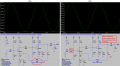
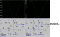
I am looking at a two-stage ce amp with negative feedback. The voltage gain with
negative feedback is ≈ 136. The input signal current is = 1mV / 3.2KΩ = 0.31μA and
the load current = 13.579mA. Ai = 43,803.

Ap = Ai * Av = 136 * 43,803 = 5,957208.

Can this be right?

Thanks
 

Attachments

Audioguru again

Joined Oct 21, 2019
6,673
The voltage gain is not 136. The load current is not 15.6mA.
The sim shows 1V peak across the 10k ohms load. Since the input is 1mV peak then the voltage gain is 1V/1mV= 1000.

Ohm's Law says the peak load current is 1V/10k= 0.1mA. You can now calculate the real current gain and power gain.
 

Thread Starter

aac044210

Joined Nov 19, 2019
178
The voltage gain is not 136. The load current is not 15.6mA.
The sim shows 1V peak across the 10k ohms load. Since the input is 1mV peak then the voltage gain is 1V/1mV= 1000.

Ohm's Law says the peak load current is 1V/10k= 0.1mA. You can now calculate the real current gain and power gain.
Thanks but you are totally wrong dude.
 

Jony130

Joined Feb 17, 2009
5,487
The input signal current is = 1mV / 3.2KΩ = 0.31μA
From where did you get this 3.2kΩ?
The input impedance of this amplifier cannot be larger than RB11||RB12 = 1kΩ||4.7kΩ = 820Ω

Sidenote.
The capital letter "K" is not for "thousand" but a Kelvin (temperature in Kelvins (300K = 26.85°C ) ).
For "thousand" we use the small letter "k" instead.
and the load current = 13.579mA.
How? If RL = 10kΩ and IL = 13.579mA from the Ohm's law we have:

VL = 13.579mA*10kΩ = 135.8V???
 
Last edited:

Thread Starter

aac044210

Joined Nov 19, 2019
178
From where did you get this 3.2kΩ?
The input impedance of this amplifier cannot be larger than RB11||RB12 = 1kΩ||4.7kΩ = 820Ω

Sidenote.
The capital letter "K" is not for "thousand" but a Kelvin (temperature in Kelvins (300K = 26.85°C ) ).
For "thousand" we use the small letter "k" instead.

How? If RL = 10kΩ and IL = 13.579mA from the Ohm's law we have:

VL = 13.579mA*10kΩ = 135.8V???
My bad, load current is 13.579 μA.
The 3.26Ω is Zin for the amp.


From where did you get this 3.2kΩ?
The input impedance of this amplifier cannot be larger than RB11||RB12 = 1kΩ||4.7kΩ = 820Ω

Sidenote.
The capital letter "K" is not for "thousand" but a Kelvin (temperature in Kelvins (300K = 26.85°C ) ).
For "thousand" we use the small letter "k" instead.

How? If RL = 10kΩ and IL = 13.579mA from the Ohm's law we have:

VL = 13.579mA*10kΩ = 135.8V???
My bad. Load current is 13.5 μA, not mA.
 

Jony130

Joined Feb 17, 2009
5,487
The circuit you show as will do not have such a low Zin in the audio frequency range. It will be somewhere around Zin ≈ RB11||RB12 = 1kΩ||4.7kΩ = 820Ω.
And yes, it is true that Ai * Av = Ap
 

Thread Starter

aac044210

Joined Nov 19, 2019
178
Hi AG:

This is the ac analysis from the sim.
I am not sure where the 1V peak is coming from.

AC Analysis.png
 
Last edited:

Thread Starter

aac044210

Joined Nov 19, 2019
178
From where did you get this 3.2kΩ?
The input impedance of this amplifier cannot be larger than RB11||RB12 = 1kΩ||4.7kΩ = 820Ω

Sidenote.
The capital letter "K" is not for "thousand" but a Kelvin (temperature in Kelvins (300K = 26.85°C ) ).
For "thousand" we use the small letter "k" instead.

How? If RL = 10kΩ and IL = 13.579mA from the Ohm's law we have:

VL = 13.579mA*10kΩ = 135.8V???
But with a negative feedback factor of approximately 4, Zin becomes 3.22KΩ?
 

Audioguru again

Joined Oct 21, 2019
6,673
My bad, me too. My simulation missed out your negative feedback pot so the output level is 150mV peak and the output current into the 10k load is 0.15V/10k= 15uA.

I added an 820 ohm input resistor to the simulation which caused the output level to drop to half so the input impedance of your circuit is 820 ohms.
 

Attachments

Thread Starter

aac044210

Joined Nov 19, 2019
178
No worries AG, it is so easy to miss one little thing with this stuff.

Yes, I have a Zin = 820Ω and Zout = RC2 = 3.9KΩ. Since there is two-stage negative feedback
is it true that the input impedance is multiplied by the feedback factor and the output
impedance is divided by the feedback factor? The factor that I calculated is 4.3, which would
change Zin ≈ 3.5KΩ and Zout ≈ 907Ω?
 

Audioguru again

Joined Oct 21, 2019
6,673
RC2 is the DC load of the second transistor. The output impedance is the 3.9k parallel with the 10k load reduced as you say by the negative feedback.

The negative feedback has already reduced the input impedance. Without the negative feedback the input impedance is about 2.4k ohms in the simulation.

Input impedance is increased by using bootstrapping which is positive feedback.
 

Thread Starter

aac044210

Joined Nov 19, 2019
178
Thanks AG. That makes perfect sense since since is(signal current) = 1mv / 820Ω ≈ 1.22μA in the sim.
Does that mean that Zout = 907Ω ?
 

Jony130

Joined Feb 17, 2009
5,487
But with a negative feedback factor of approximately 4, Zin becomes 3.22KΩ?
No, in this particular case the negative feedback can only increases the resistance seen from base into BJT.
RinT = (β +1)*(re+RE1)*(1 +Aol*feedback factor)

But negative feedback has no effect on Rb11 and Rb12 therefor Zin = Rb11||Rb12||RinT ≈ Rb11||Rb12
 

Thread Starter

aac044210

Joined Nov 19, 2019
178
No, in this particular case the negative feedback can only increases the resistance seen from base into BJT.
RinT = (β +1)*(re+RE1)*(1 +Aol*feedback factor)

But negative feedback has no effect on Rb11 and Rb12 therefor Zin = Rb11||Rb12||RinT ≈ Rb11||Rb12
Thanks Jony
 

Jony130

Joined Feb 17, 2009
5,487
I did some calcs to derive what I think should be Zout.

Zout = RC2||(RF1 + RF2A + RF2B)|| RL = 2.146KΩ
You cannot include RL resistance in the equation because Zout is a resistance seen by RL (resistance seen from RL into the the amplifier output).

To find the Zout after you apply negative feedback the voltage feedback in series with the input ( voltage-series feedback).
You need to find the loop gain.

We can use an approximate method to find the loop gain:

We first need to find the open-loop gain AOL using this circuit:
untitled.PNG


For Ic1 = Ic2 ≈ 1mA and β = 280... we have: re1 = re2 = 26Ω hence:

AOL ≈ (Rc1||RB21||RB22||(β * re2))/(re1+RF1) * (Rc2||RL||(RF1a+RF2a))/re2 = 8.6 V/V * 82V/V ≈ 705 V/V

And the loop gain is loop gain ≈ (705 V/V *(47Ω/8.77kΩ)) ≈ 3.8


Therefore Zout ≈ (Rc2||(RF1a+RF2a))/(1 + loop gain) ≈ 2.7k/4.8 ≈ 560Ω
 
Last edited:
Top