Facebook
 Google
 GitHub
 Linkedin
Hello,
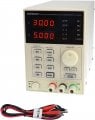
Is there a ready made device that can be used to limit the current being consumed by any load. Specifically, I would like to limit the current going out from a car battery for a home project. I'm looking for something that is adjustable where I can select what is the maximum current that can be withdrawn from the battery.
I appreciate your help.
Best Regards,
Tariq