current limit on 1W led spots (powerled)

Thread Starter

vult-r

Joined Jan 10, 2020
7
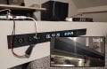
Aiming to control four 1W powerleds. on default they come with some AC-DC 300mA led-drivers, 3.3v
probably those things have some sort of current limiter onboard. i measure 290mA on each LED spot.

1.jpg
pic1. : the default led driver

my first setup had a 6channel relay board to put 230V on each individual led-driver. The relay coils caused strange interferance (EMF/EMI?) ghost triggering all capactive touch sensors and messing with 3.3v data wires.. I tried isolating stuff (own PSU on relay ; two isolated circuits) but nothing helped, and i abondoned that idea.

now my current setup is build on NPN transistors switching step-down-convertors (ams1118 -800mA) to get the needed 3.3v on/off the LED spots.

3.jpg

concern is that the spots get noticable warmer, and the current i measure on A,B,C, and D are:

~350-360 mA when turning 2 spots on. (20% above default)
~320-330 mA when turning 4 spots on.

what i also notice is that the entire circuit has voltage drops when i put all 2 or 4 spots ON.


i makes me i wonder if this is an OK practice to go with..

as the led spots are clearly trying to take more then 300mA, is there anything easy to limit the DC current back to below 300mA ? without changing voltage
 

Attachments

ElectricSpidey

Joined Dec 2, 2017
2,757
Well you have eliminated the current limiting, so you need to add some sort of current limiting (resistors), or at the very least lower the voltage to the LEDs.

You probably should have replaced the default drivers with step down modules with current regulation, instead of constant voltage types.
 
Last edited:

ronsimpson

Joined Oct 7, 2019
2,985
AC-DC 300mA led-drivers
This power supply makes 300mA and the voltage is what ever it is. This supply regulates current not voltage.

You used a (ams1118 -800mA) which limits the voltage to 3.3 and does not limit the current. On some LEDs the current will be too high and on some the current will be too low.

LEDs are a current device not a voltage device. They respond to current not voltage. It would be better to say your LEDs are 1 watt devices or to say they are 300mA LEDs, (which might have a voltage in the 2.8 to 3.8 volt range.
 

Thread Starter

vult-r

Joined Jan 10, 2020
7
Thanks guys i understand the led driver a lot better.

So i wonder now, how bad is ignoring the over-current, without putting some limit, currently running 60mA above default?

What kind of resistor could help me out? i'm a bit clueless..

Could this 'XL4015' be usable? seems to have adjustable current-limit and takes 5v input,
but described as a lithium battery charger.

001.jpg
pic. XL4015

Or would a solid-state relay maybe easy fix the stuff without magnetic coil interference?
that way i can just put back the default led drivers..
 

Attachments

ElectricSpidey

Joined Dec 2, 2017
2,757
Are you sure the relays were causing the trouble and not the drivers?

Those XL4015s should work, just be sure to get one that will take the 5 volts in because I looked at some of those modules, and they say min 8 volts, others say 4…

Solid state relays and the original drivers should do the job, as long as you are sure it wasn’t the drivers causing the problem.
 
Last edited:

Thread Starter

vult-r

Joined Jan 10, 2020
7
Are you sure the relays were causing the trouble and not the drivers?
not sure , maybe if switching the LED drivers on/off can somehow mess the entire 5V10A PSU -> messing the entire 5v circuit?

324.jpg

1. i just put an additional 5V supply on the relay's 'jd-vcc' in attempt isolating the the magnetic coils .
2. then i tried disconnecting all logic lines from the relay by putting an additional microcontroller.
3. last i tried putting the 230v connected to relay on a different powersocket then the 5v10A PSU.
then i gave up.. without any idea what was going on; displays crashing, buttons firing without reason etc.

gonna try a 6channel solidstate relay, probably here in 1-2 weeks, maybe it can.. i will post how that go.

if not, its probably the right version of all the XL4015's out there. thanks for noticing.
 

Thread Starter

vult-r

Joined Jan 10, 2020
7
so you need to add some sort of current limiting (resistors)
i dont have much stock, the lowest resistors in my kit are those small carbon 100ohms 0.25w ,
based on P=v*v/R the thing is now loaded within it's specs (3.3x3.3/100=0.10w) ?

res-100.jpg

placed on the 3.3v line between ams1117 and ledspot , things run wayy cooler and dropped to an amazing low 7mA
steady but.. ofc really dim and moody light. nowhere near the power it had.

is this something i can get away with for now ? untill i fix it with either a solidstate relay, or replace with some
lower ohm resistor with a higher powerrating?
 

BobTPH

Joined Jun 5, 2013
8,804
Well of course it is going to run cooler at 7mA than at 320! But not produce much light.

Go to the buck converters with current limit and limit the current to something less than 300mA. Use one converter per LED. If you run two LEDs off a single converter they will not share the current equally.

Bob
 

Thread Starter

vult-r

Joined Jan 10, 2020
7
I ordered those 1.5's as well, thanks.

Just fiddled with the stuff, and figured that i could also place the 3.3 stepdown's before the NPN transistors
(5V -> 3.3V -> NPN -> Ledspot)

Then driving PWM signal on the base of the NPN transistor, seems to cut the current-flow efficiently to wherever i want,
and there could be software control for custom dim-levels as a bonus.

so probably placing one big 2A stepdown , connected to 4 NPN's , connected to 4 leds ,
this or just placing fixed 1.5ohm in current setup , im good thanks.
 
Top