cross-over cancellation method

Thread Starter

electronicsenjoyer089

Joined Feb 24, 2025
182
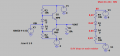
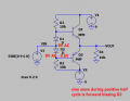
Hello all, i was simulating this push-pull stage, where the cross-over gets cancelled.
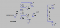
But i didnt understand how it works, like who's forward biasing here the diodes? the power supply of 9V and -9V? ( like the circuit i show near to it )
or the signal vin is responsible for the forward biasing? and if its the power supply then why the vin doesnt matter? like ur not applying 2 signals?
 

Attachments

ericgibbs

Joined Jan 29, 2010
21,390
hi 089,
The +/-9V via the R2,R3 current creates a voltage drop across each diode of approx 0.65V
E
Post your LTS asc file.
 

Thread Starter

electronicsenjoyer089

Joined Feb 24, 2025
182
hi 089,
The +/-9V via the R2,R3 current creates a voltage drop across each diode of approx 0.65V
E
Post your LTS asc file.
But something else isnt clear to me, like we are applying an AC signal ok? and this is also forward biasing the diodes in same time no? or the signal given by the D.C source has always "priority" over the signal u give in input? i can explain again in case i wasnt clear.
 

ericgibbs

Joined Jan 29, 2010
21,390
this is also forward biasing the diodes in same time no?
hi,
The diode bias voltage to each transistor is just enough to start the transistor conducting in it linear operation mode.
Without that bias, you get what is called 'cross over distortion'.
E
 

Thread Starter

electronicsenjoyer089

Joined Feb 24, 2025
182
hi,
The diode bias voltage to each transistor is just enough to start the transistor conducting in it linear operation mode.
Without that bias, you get what is called 'cross over distortion'.
E
yeah this i get it, but my question is different, like i get it that without bias i would get cross over distortion and its where the vin is beetwen -0.7V and 0.7V so none of the transistor are conducting, but my question is kinda different, i can explain again in detail maybe if u didnt get me
 

Thread Starter

electronicsenjoyer089

Joined Feb 24, 2025
182
hi,
This shows when the diodes are shorted out, ie: no VBE bias voltage.
Note the cross-over distortion around 0V on Vout.
E
View attachment 347745View attachment 347746
who makes the diode to be shorted? and in that case what happens? the bias voltage is given from who? these diodes shouldnt be able to have always 0.7v on them, so even while the sine wave is at 0V the transistor are still conducting?
 

BobTPH

Joined Jun 5, 2013
11,463
The signal, as you have it connected, will force its voltage at the junction of the two diodes. The bases will then be at Vin +0.65V and Vin - 0.65V. In a real circuit , there will be a series resistance in the signal path, so the voltages at the bases will not swing as far as the signal.
 

Thread Starter

electronicsenjoyer089

Joined Feb 24, 2025
182
The signal, as you have it connected, will force its voltage at the junction of the two diodes. The bases will then be at Vin +0.65V and Vin - 0.65V. In a real circuit , there will be a series resistance in the signal path, so the voltages at the bases will not swing as far as the signal.
sorry but one thing? who's responsible here for the polarization of the diodes? the D.C power supply or the vin? ( sinusoidal wave ) this is what i dont get
 

Thread Starter

electronicsenjoyer089

Joined Feb 24, 2025
182
lets analyze the 2 cycles of the sine wave separately ok? during first cycle, the positive half, this happens: the positive cycle is forward biasing the diode, or the d.c forces that diode to be always forward biased?
 

Attachments

Thread Starter

electronicsenjoyer089

Joined Feb 24, 2025
182
The signal, as you have it connected, will force its voltage at the junction of the two diodes. The bases will then be at Vin +0.65V and Vin - 0.65V. In a real circuit , there will be a series resistance in the signal path, so the voltages at the bases will not swing as far as the signal.
what i understood is:

1) during positive half cycle D2 diode is polarized directly, and on the cathode i will have VIN-0.7V
2) during negative half cycle D1 diode is polarized directly, and on the anode i will have VIN+0.7 ( since the rule says that the diode, in order to conduct, the anode needs to be at higher potentional of the cathode by 0.7 )

am i right?

but with that said, i dont have also to look at the d.c voltage? that one dont do anything to the diodes? tell me if im not clear, i can explain again and again.
 

BobTPH

Joined Jun 5, 2013
11,463
No, the two diodes will both be always be forward biased until the input signal gets close to ±9V. The biasing current comes from the two power sources.

That does not mean the Vbe of the transistors isn’t changing, because the emitters are following the input signal.

Change your input source to a ramp from -9V to +9V and plot the voltage across each diode.
 

Thread Starter

electronicsenjoyer089

Joined Feb 24, 2025
182
No, the two diodes will both be always be forward biased until the input signal gets close to ±9V. The biasing current comes from the two power sources.

That does not mean the Vbe of the transistors isn’t changing, because the emitters are following the input signal.

Change your input source to a ramp from -9V to +9V and plot the voltage across each diode.
ok, so the power supply is always forward biased cus of the voltage given by the power supply, but lets assume we are in the case where the sine wave is approaching the 9V, so it assumes that value at a certain point, at this point the 9V given by power supply isnt sufficient because the ac signal wins over the d.c voltage no?
 
Top