Facebook
 Google
 GitHub
 Linkedin
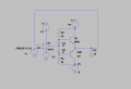
ok so now i got that on the cathode i got 9VDC, while at anode i got 8.3V, so -0.7VChange your signal to be 9V DC. Now what is the voltage across D1? Hopefully you can do that in your head.
cross-over cancellation method
- Thread starter electronicsenjoyer089
- Start date