Creative Inspire Sound system T3030

Thread Starter

gopalyajur

Joined Jan 3, 2010
100
Hello all,

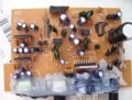
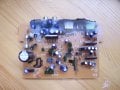
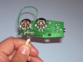
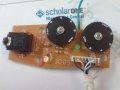
I have creative Inspire sound system (http://www.testfreaks.com/pc-speakers/creative-inspire-t3030/). I initially had some trouble with the volume control which after replacing seemed to work properly.

Now the system does not work at all. The power LED in the remote control is permanently OFF and there is no sound at all. I checked the power supply section in the board and it seems to work properly. I dont know what else could be wrong. I have very basic knowledge in electronics and be very happy if someone could show some pointers in solving the issue with my system.

Thanks in advance.

Gopal

P.S. I tried to contact the service division of Creative labs for the circuit diagram for the system. But, they informed me that circuit diagrams for their products will not be given to their customers.
 

retched

Joined Dec 5, 2009
5,208
This may be obvious, but have you checked the battery voltage and installation direction?

Also, If the led is burned out, by chance and they used it in series with the rest of the transmission circuit, It will not work.

See if you have any voltage at the anode when you press and hold the button. Multimeter RED lead to the anode of LED and black lead to battery (-)

If you have another led, you could try replacing it.
 

R!f@@

Joined Apr 2, 2009
9,918
U do not need a schema to fix those simple things.
If you can solder, desolder and test components. Then all u need is a camera to take some nice closeups.
I can do the rest.
 

Thread Starter

gopalyajur

Joined Jan 3, 2010
100
Thanks retched and Riffa for your response.

Retched I did check the voltage between the anode of LED and the -ve rail if the supply. I get almost 18 V and LED is not burned out. Its simply that the is no sound output.

@ Riffa, I will try to upload a good quality pic of the PCB.


Regards,

Gopal.
 

SgtWookie

Joined Jul 17, 2007
22,230
Gopal,
It is very difficult to take good pictures of circuit boards.

The best lighting is outdoors on an overcast day. It is very bright light that is very diffused. The subject is then very well and evenly lit from all angles, and the camera lens is open wide for much better focusing.

Don't try to use a flash, as the resulting photos will be very harsh (too much contrast).

Don't try to get in closer to the circuit board than the focal length of the camera. If you have a "macro" mode, use it. Fuzzy, blurry photos will not be of any help.
 

Thread Starter

gopalyajur

Joined Jan 3, 2010
100
thanks sgtwookie for suggestions.

Please find the attached the images of the PCBs in pdf.
The larger board in the amplifier and the smaller board is the remote control (connected to amplifier through wires).

Thanks once again.

Gopal
 

Attachments

R!f@@

Joined Apr 2, 2009
9,918
Ok..If you are fast enuf we can get this done tonight...
Ur photo's are out of focus.
I need a focused ones, cause I will be marking them for you to check, so basically the photo is all I have to fix it.

By the way just redit the post and attach new pics, check them for correct focus before attaching.

One more thing I like to know is where is the on off switch
 

SgtWookie

Joined Jul 17, 2007
22,230
The on-off switch is likely in the rotary volume control pots. I have a few of those in my "Ye Olde Junque' Boxe" and they are pretty finicky. A blast of some contact cleaner will help them considerably.
 

Thread Starter

gopalyajur

Joined Jan 3, 2010
100
Thanks for the reply.

The ON / OFF switch is broken. In the smaller PCB you see a green wire, I have just connected the switch points with a small green wire.

I will try to upload better picture soon.

Gopal
 

R!f@@

Joined Apr 2, 2009
9,918
I really donno how u are taking the pic.
You better do it in sun light.
The solder side has flash over.
I cannot make it. Here do not use flash, take it in sunlight without direct reflection to the camera.
The solder side will be used to mark check points for u to see what is wrong
When the lighting is correct u are out of focus.

I am sorry, It is difficult with out of focused pictures.

Here is something I like you to check.

Never power without the heat sink as that amp IC will over heat at idle.
Mount the heat sink and power up.
Measure the DC voltage at the big capacitor of the amp supply
post the result
 

Thread Starter

gopalyajur

Joined Jan 3, 2010
100
Sorry, Riffa for the bad quality picture.
My friend helped me by taking pictures with his camera and it seems to be better.

I dont have the heat sink with me now and the chip is not getting warm until now. Still problem with the power it seems.

I checked the voltage at the big capacitor after the bridge rectifier and its 18 V. And I measure 12 V across the Zener diode. The capacitors (C55 and C56) close to the remote jack got damaged when I tried to remove the hot glue.

There is no positive voltage in remote circuitry. However, if I connect the output from R25 (5.6 ohm) close to C55 and C56 to volume control switch the LED turned ON and the there was sound output for some time and the resistors R53 and R60 in remote control became warm.

Please do let me know how to proceed.

Regards,

Gopal.
 

Attachments

R!f@@

Joined Apr 2, 2009
9,918
The Power amp chip needs to be on the heatsink to proceed. Since it is warming up, it won't take soon to thermal runaway.
Get me the no. on the chip.
Another way to proceed with power is to have ur finger always placed on the chip to monitor heat, if it is too hot to touch, immediately power down to cool it, this way by taking breaks, voltage can be measured.

I'll be back with in a few minutes.
My sis is admitted at the hospital, I just came home from there.
Have to care of somethings.

Be here if you can.

PS..pictures are fine now
 

Thread Starter

gopalyajur

Joined Jan 3, 2010
100
Thanks Rifa. As i mentioned before I don't have the heat sink now. I will try to careful during the measurements.

The chip is TDA 7378.

Sorry, to know about your sister. If your too busy, we could also do it tomorrow or other time at your convenience.
 

R!f@@

Joined Apr 2, 2009
9,918
thanks mate. Baby is on the way on 27th hopefully. Nothing serious, usual check ups. :p
Let me check the data and let u know what to do in a while.

TDA7378 ?
Are u sure it's not TDA7376 ?

Can't seem to find data for a 78 ?
 
Last edited:

R!f@@

Joined Apr 2, 2009
9,918
Ok then. see the PIC


I did not get a data, but based on my experience on these type of amps.
What you have is a quad power amp.

The red line shows Positive supply path and black is ur common reference which is GND
IC will get extremely hot if it is faulty, but in minor cases not.
If you get 18 V at cap then you have a working supply.
Keep in mind the temp monitoring method I said, Voltage measurements are taken with reference to GND for points 1 and 2.

First clean the area in the circle, it seems u have solder bridges, connecting one Vcc pin to an output.

Power up, keep one finger at the tab of the IC and measure voltage at

# Point 5, which are Vcc1 and Vcc2 for the Power stages of the IC.
U should get 18V or so.

# point 1 and 2

Now measure Points 3 and 4, measure across them not referenced to GND. As 3 and 4 points are for woofer and is a bridge output.
Here you will have some voltage if referenced to GND under normal conditions, but never across them what so ever.

If IC is getting hot to touch really fast then u need to replace it. It is faulty

Post back
 

Thread Starter

gopalyajur

Joined Jan 3, 2010
100
Thanks for the suggestions.

Checked the area under circle for continuity-no bridges or short.
Anyway I have to listen to expert :) - mulitmeter reads 18V

point 5 reads 18 V too

point 3 and 4 no voltage but when referenced to ground 18 V

waiting for your comments :)
 
Top