create JK-FF with T-FF and 2->1MUX

Thread Starter

Gyyy y

Joined Jan 1, 2017
8
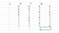
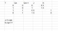
Hey, im having a problem in making JK-FF with T-FF and 2-1MUX, any one have an idea how to create it?

also, it will be helpful if you also tell me what guiding you to the sulotion of those kind of questions.
for example, if i could use a logic gates then i were probebly will work with a Truth Table and try to get a function .

Hope its clear, thanks!
 

crutschow

Joined Mar 14, 2008
34,452
Generate a state-table that shows all the combination of JK inputs along with the required FF toggle input to get the desired FF output after the next clock pulse.
That will show how you need to connect the mux to get the required response.

If you still have problem, post the table you generated, and we can help you from there.
 

crutschow

Joined Mar 14, 2008
34,452
Then add to the table what the toggle FF input needs to be for each of the states.
Then you can determine how to generate that input from the JK inputs.
 

RBR1317

Joined Nov 13, 2010
714
i uploaded the excitation table i made.
The excitation table examines the characteristic equation of the flip-flop to document what control input combinations (T or J,K) produce each of the four possible Q output next-state transitions (0→0, 0→1, 1→0, 1→1). Unless your excitation table shows the next-state transitions, then it is not an excitation table.
 

Thread Starter

Gyyy y

Joined Jan 1, 2017
8
this one is better?
if not ,could you give me an example?
as i said i need to create JKFF with TFF and MUX 2-1 only, so i dont understand what to do with this excitation table.
this subject is new for me so i really not sure what to do.
thanks again.
 

Attachments

RBR1317

Joined Nov 13, 2010
714
So here is a re-draw of your excitation table to make it more readable. Note that it superimposes the JK and T excitation tables so that the next-state transitions coincide. Also note that from the problem statement you are trying to make the T-FF produce the same transitions as the JK-FF would have. Your JK-FF circuit will have J & K inputs and a Q output. Now observe from the excitation table that the T input of the T-FF is the same as the J input when Q is 0 and the T input of the T-FF is the same as the K input when Q is 1. So does that suggest how to connect the J&K inputs, the 2-1 mux, and the T-FF in order to simulate a JK-FF?
Screenshot from 2017-01-02 17-05-17.png
 

Thread Starter

Gyyy y

Joined Jan 1, 2017
8
im sorry but i still not understand how to make the circutes =/
if you clould show me a draw of the circuits it will be much more helpfull.

thanks alot.
 

RBR1317

Joined Nov 13, 2010
714
Would suggest you draw the circuit like this; however, your assignment is to figure out how to connect the multiplexer & T flip-flop together.
Screenshot from 2017-01-03 12-16-50.png
 
Top