Create a shift on a square signal

Thread Starter

kanoun

Joined Jan 29, 2015
41
Hi guys,

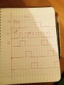
I need to create a 3 signals that are shifted from a reference one (see attached) S1 is the reference one, H is the clock. I'm trying to use a shift regester. My understing is that I need a in serie out series shift register. Is that true? anyway could you advise how to do so.
I'm really not an expert in electronics.
Many thanks for your help
 

Attachments

dl324

Joined Mar 30, 2015
18,326
Hi Kanoun,

How is S1 being generated? Are there any constraints on how S2, S3, and S4 are generated?

Is this a home work problem?
 

dl324

Joined Mar 30, 2015
18,326
Is using a couple of flip flops and 4 AND gates acceptable?

Is the last waveform drawn correctly? Seems like it should be HI for the first half cycle of H.
 

Thread Starter

kanoun

Joined Jan 29, 2015
41
Is using a couple of flip flops and 4 AND gates acceptable?

Is the last waveform drawn correctly? Seems like it should be HI for the first half cycle of H.
I did a mistake with the last one you're right.no it is not a homework ... I'm too old for homework :)
 

dl324

Joined Mar 30, 2015
18,326
Hi kanoun,

You're device will work. Could also use half of a CD4015 or a CD4013 plus CD4011 (which I think is more interesting).
 

ScottWang

Joined Aug 23, 2012
7,501
1. What is the circuit uesed for?
2. The S2 is going high when the S1 is at the falling edge.

Assuming that there are S3 and S4 below the S2:
3. S3 is going high when S2 is at the falling edge
4. S4 is going high when S3 is at the falling edge

S1 output is repeating:
5. S1 is going high when S4 is at the falling edge.

So, does what you want is a johnson counter?

johnson counter d flip flop.
 

crutschow

Joined Mar 14, 2008
38,503
If you want to use the SN74HC595, then connect the RCLK and SCLK together to the H signal.
Connect S1 signal to the SER input.
Outputs QA, QB, and QC should have the signals you want.
 

dl324

Joined Mar 30, 2015
18,326
I do not see where the "H" signal is being generated.
It's equally unclear how S1 is being generated (aside from 555 timer without a schematic) and how it's waveform is being synch'ed to H. If the HI/LO times aren't controlled sufficiently, using a shift register might not give the desired results.

Much simpler to use a couple flip flops and a pack of AND gates.
 

bertus

Joined Apr 5, 2008
22,922
Hello,

There is a discrepance in your drawing.
You are stating 50 seconds for a cycle, I come to 40 seconds:
crenaux_remark.jpg

When you have the "H" signal, use it to clock a 4017 and reset it at the wanted number of pulses.

Bertus
 

Thread Starter

kanoun

Joined Jan 29, 2015
41
Yes yo
Hello,

There is a discrepance in your drawing.
You are stating 50 seconds for a cycle, I come to 40 seconds:
View attachment 84055

When you have the "H" signal, use it to clock a 4017 and reset it at the wanted number of pulses.

Bertus
yes you're right ... It is a mistake when I drowed the signals :) ... Anyway Ill use the 4017 I finally understood how it's work ...
 
Top