 Facebook
 Google
 GitHub
 Linkedin
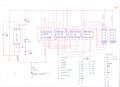
Can anyone help me to install counter to count down from 10 to 0 using 555 & 2 of 74192 & 2 of 7447 + 2 seven segment the problem I face is to make tens digit and unit digit as it counts from 10 to 0 so please if anyone can help me.
Counter
- Thread starter Abdelrahman95
- Start date
| Thread starter | Similar threads | Forum | Replies | Date |
|---|---|---|---|---|
|
|
Logic D | Homework Help | 53 | |
|
|
12hr clock in quartus showing am and pm with switch | Homework Help | 10 | |
|
|
MOD 12 Up Down Counter | Homework Help | 4 | |
| F | 74192 counter up/down | Homework Help | 30 | |
|
|
connecting the blocks of the electrical circuit of the Muller Geiger counter? | General Electronics Chat | 7 |


