Counter to increment display once for every twenty switch inputs

elec_mech

Joined Nov 12, 2008
1,500
Hi the reason for considering a rotary switch is to prevent the operator from accidentally changing the grid setting halfway through a grid.
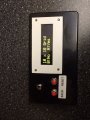
Adding a dedicated switch does just the opposite - makes it easy to accidentally change the grid setting while taking readings. The program, as it is currently written, only allows the user to select the grid size at power up. Once selected, the only way to change the grid size is to cycle power (which also resets the count to zero).

At the end of the row the 'Row No.' would increment by one and the 'Sample No.' would reset to zero.
Already done.

At the end of the grid the 'Sample No.' would retain its count, so say on a 20 x 20 grid the display would show Sample No. 20 Row No 20.
Ah - I'll need to tweak the program then. Shall we have the program stop counting once the last grid measurement is taken? In other words, if the user has reached 20 x 20, shall we have the program stop and wait for either a reset or a power cycle (program ignores further trigger button presses once 20 x 20 is reached)?
 

Thread Starter

macke

Joined Oct 12, 2014
65
Hi the only decision then is on the type of switches to use to select the grid size. It's needs to be easy and must have a way to prevent accidental reset halfway through a grid.
Re the end of the grid reading, yes it should stop. One guy suggesting adding a flashing LED as well to indicate end. I guess that would require another output and might be a bit of overkill.
macke
 

elec_mech

Joined Nov 12, 2008
1,500
Hi the only decision then is on the type of switches to use to select the grid size.
Are you talking about which switch to purchase or operation? Assuming the latter . . .

As the program is currently written, at power-up the user presses the reset button (a momentary N.O. switch) to scroll through the three grid sizes. Once the desired grid size is shown, the user presses the trigger (record) button to select that grid size.

If pressing the trigger button will cause problems (taking a recording when you don't want to), then we have two options that come to mind off the bat. A) add a second 'enter' switch (also momentary N.O.) or B) have the user press the reset button briefly to scroll through the grid sizes then have the user press and hold the reset button for, say, 2-3 seconds to select the grid size.

Certainly option a is easier, but . . .

One guy suggesting adding a flashing LED as well to indicate end.
If we go with option b, that leaves us with a free pin to connect an LED to. Another option to consider is flashing the LCD.

. . . must have a way to prevent accidental reset halfway through a grid.
A couple of ideas here - one is to force the user to hit the reset button something like three times in a row. So if the reset button is pressed once, the LCD shows:

"Reset Count?"

If user presses reset again, the LCD could show:

"Are you sure you want to reset the count?"

And if the user presses a third time, the count is reset to zero.

If the user presses the trigger button anytime before the third press, the count continues as before.

We can do other things like use another 'enter' button to select yes to reset and/or increase or decrease the number of times the user must confirm a reset, but I think the example above covers against accidental resets nicely. No pride of authorship however and I'm not the one using it, so let me know what you'd prefer.
 

Thread Starter

macke

Joined Oct 12, 2014
65
Are you talking about which switch to purchase or operation? Assuming the latter . . .

As the program is currently written, at power-up the user presses the reset button (a momentary N.O. switch) to scroll through the three grid sizes. Once the desired grid size is shown, the user presses the trigger (record) button to select that grid size.

If pressing the trigger button will cause problems (taking a recording when you don't want to), then we have two options that come to mind off the bat. A) add a second 'enter' switch (also momentary N.O.) or B) have the user press the reset button briefly to scroll through the grid sizes then have the user press and hold the reset button for, say, 2-3 seconds to select the grid size.

Certainly option a is easier, but . . .


If we go with option b, that leaves us with a free pin to connect an LED to. Another option to consider is flashing the LCD.


A couple of ideas here - one is to force the user to hit the reset button something like three times in a row. So if the reset button is pressed once, the LCD shows:

"Reset Count?"

If user presses reset again, the LCD could show:

"Are you sure you want to reset the count?"

And if the user presses a third time, the count is reset to zero.

If the user presses the trigger button anytime before the third press, the count continues as before.

We can do other things like use another 'enter' button to select yes to reset and/or increase or decrease the number of times the user must confirm a reset, but I think the example above covers against accidental resets nicely. No pride of authorship however and I'm not the one using it, so let me know what you'd prefer.
Hi thank you for this. I think option A (2 switches is good and flashing the display at the end of the grid should suffice. I also like the idea of 'three strikes and your out' by warning the user re the reset.
I guess if the user accidentally presses the new ENTER button halfway through a grid nothing will happen.
Macke
 

elec_mech

Joined Nov 12, 2008
1,500
I guess if the user accidentally presses the new ENTER button halfway through a grid nothing will happen.
Correct - unless you want to have the user press reset first then enter twice (or reset twice then enter). Or enter could be used to go back to the grid screen without pressing the trigger and taking a measurement. That might be best.

Perhaps for switch naming conventions, we could go with:
Reset/Select
Back/Scroll

The second button could then be used to scroll through the grid sizes at power up and the reset button used to select the desired grid size. During operation, reset is used to reset and scroll is used to go back to the grid screen.

Might be best to just name them 'reset' and 'back'. At power up, we can tell the user to press back to scroll and reset to select (enter).

Thoughts?

What you think about the display showing:
Sample # of 20
Row # of 20

Currently, the program is written something like:
Sample No: #
Row : #

The former allows the user to see what the selected grid is at all times.
 

Thread Starter

macke

Joined Oct 12, 2014
65
Correct - unless you want to have the user press reset first then enter twice (or reset twice then enter). Or enter could be used to go back to the grid screen without pressing the trigger and taking a measurement. That might be best.

Perhaps for switch naming conventions, we could go with:
Reset/Select
Back/Scroll

The second button could then be used to scroll through the grid sizes at power up and the reset button used to select the desired grid size. During operation, reset is used to reset and scroll is used to go back to the grid screen.

Might be best to just name them 'reset' and 'back'. At power up, we can tell the user to press back to scroll and reset to select (enter).

Thoughts?

What you think about the display showing:
Sample # of 20
Row # of 20

Currently, the program is written something like:
Sample No: #
Row : #

The former allows the user to see what the selected grid is at all times.
Hi yes I agree with all of this. The swapping of the functions of the two buttons makes perfect sense as does the wording on the display. I have ordered some of the parts already, albeit to assemble on a breadboard initially.
Macke
 

Thread Starter

macke

Joined Oct 12, 2014
65
Hi yes I agree with all of this. The swapping of the functions of the two buttons makes perfect sense as does the wording on the display. I have ordered some of the parts already, albeit to assemble on a breadboard initially.
Macke
Hi just had a question posed. Very occasionally we take a sample reading which we are not happy with and will repeat so making 21 samples in a 20 sample row. I guess as the only connection to the unit is via a jack plug to the NO sample switch we could just unplug it for this extra reading.
Macke
 

elec_mech

Joined Nov 12, 2008
1,500
Hmm, an interesting problem. The circuit has no impact on the recorder, so you can take as many samples as needed, but the grid location will be off. Now, since the purpose of the circuit is to help the user keep track of where they are (I assume), we could add a feature to the back button. Since it is currently only used to back out of the reset mode during the recording, we could have it subtract a sample.

So, with a 10 x 10 grid, let's say the user is at sample 10, row 2. They press trigger to take a measurement and the display now shows sample 1, row 3, but the user doesn't like the data and decides to take another measurement of the same spot. We can simply have them press the back button once (or three times like the reset button to limit accidental button presses) and the display will count back one (sample 10, row 2). The button will already be label 'back' which should help from a user's point of view. :)

Since the data recorded and the circuit (grid display) aren't intrinsically linked, the user can hit the back button either right before or right after taking a second measurement of the same spot and the grid display will still be accurate.

Would this help?

We can limit how far back the user can go if needed, e.g., the first time the back button is pressed, the count goes back by one, but no more until the trigger button is pressed again. You may or may not want to limit this though. You'll have to discuss this with your team.
 

Thread Starter

macke

Joined Oct 12, 2014
65
Hi I like
Hmm, an interesting problem. The circuit has no impact on the recorder, so you can take as many samples as needed, but the grid location will be off. Now, since the purpose of the circuit is to help the user keep track of where they are (I assume), we could add a feature to the back button. Since it is currently only used to back out of the reset mode during the recording, we could have it subtract a sample.

So, with a 10 x 10 grid, let's say the user is at sample 10, row 2. They press trigger to take a measurement and the display now shows sample 1, row 3, but the user doesn't like the data and decides to take another measurement of the same spot. We can simply have them press the back button once (or three times like the reset button to limit accidental button presses) and the display will count back one (sample 10, row 2). The button will already be label 'back' which should help from a user's point of view. :)

Since the data recorded and the circuit (grid display) aren't intrinsically linked, the user can hit the back button either right before or right after taking a second measurement of the same spot and the grid display will still be accurate.

Would this help?

We can limit how far back the user can go if needed, e.g., the first time the back button is pressed, the count goes back by one, but no more until the trigger button is pressed again. You may or may not want to limit this though. You'll have to discuss this with your team.
Hi I like the idea of using the back button, but yes we should limit it to a single shot. Looking at the design I should be able to mount in such a way that it would be difficult to accidentally press any buttons.
Just one point that passed me by. At the start the counter needs to read Sample 0 Row 1 and increment to Row 2 after 20 samples if on a 20 x 20 grid.
Macke
 

elec_mech

Joined Nov 12, 2008
1,500
I was able to program another PICAXE to work just like the AXE133 with an LCD I had, so I put together a demo circuit to debug the code. I *think* I've worked out the bugs. Code is a attached - just remove the .txt and open with the PICAXE programmer. A short demo video below:


If you're in one of the reset or back sub-menus and hit the trigger, you'll exit whatever sub-menu you're in, the count will increment, and the display will update to reflect the count.
 

Attachments

Thread Starter

macke

Joined Oct 12, 2014
65
I was able to program another PICAXE to work just like the AXE133 with an LCD I had, so I put together a demo circuit to debug the code. I *think* I've worked out the bugs. Code is a attached - just remove the .txt and open with the PICAXE programmer. A short demo video below:


If you're in one of the reset or back sub-menus and hit the trigger, you'll exit whatever sub-menu you're in, the count will increment, and the display will update to reflect the count.
Hi all looks good thank you. I am waiting for a kit to allow me to breadboard the circuit. I have ordered an Aztec MCU kit which includes a programming cable and a 20M2. Also waiting for the OLED display. Once I am happy I will get the smaller chip, programme it and transfer it to a veroboard.
Macke
 

Thread Starter

macke

Joined Oct 12, 2014
65
Hi all looks good thank you. I am waiting for a kit to allow me to breadboard the circuit. I have ordered an Aztec MCU kit which includes a programming cable and a 20M2. Also waiting for the OLED display. Once I am happy I will get the smaller chip, programme it and transfer it to a veroboard.
Macke
Hi I passed a copy of the video on to my colleagues and they are all very enthusiastic about it. Do you have a final schematic for it. As said I will be programming it via a cable. Can't wait to get started.

Ken
 

Thread Starter

macke

Joined Oct 12, 2014
65
Hi all done and working. Absolutely brilliant!!!!!
Thank you for your very kind assistance elec_mech
Ken

I can't seem to attach a pic of the finished unit. I will upload it later.
 

Thread Starter

macke

Joined Oct 12, 2014
65
Hi it's me again. The counter is working great. I am considering building a gradiometer for geophys surveying and would like to pick your brains once again if I may. There is a circuit published some years ago by Carl Moreland and a kit of parts is available from the the manufacturers of the fluxgate sensors, Speake & Co.. Part of the circuit uses an SCL007 IC, also from Speake &Co, that can output to a data logger. How easy would it be to connect it to the PICAXE datalogger AXE110p.
Macke
 

Attachments

elec_mech

Joined Nov 12, 2008
1,500
macke,

I'd suggest starting a new thread - you'll get more help this way. For this particular project, you may also want to post this question to the PICAXE experts on the PICAXE forum. This isn't to say I won't try to help, but I don't think you want to rely solely on me.

I'm trying to find a datasheet on the SCL007 but no dice so far. There is an app note, but that's about it. The PICAXE AXE110p appears to accept 2-4 digital or analog inputs. According to the app note, pins D0-D7 transmit digital data such that D0 is LSB and D7 is MSB. I'm only guessing here, but I think that means the SCL007 outputs a digital 8-bit signal to represent to 256 values (technically 0 to 255) with the SIGN pin used to represent + or -, so -255 to +255 or 512 values. Again, this is only a guess.

If that is the case, the AXE110p probably won't work as it only has 4 inputs, not 9. However, you should be able to use the design to make your own circuit that would accept 9 inputs and store the data onto either the PICAXE's internal EEPROM memory or onto an external IC like the AXE110p appears to do. If the source code is handy for the AXE110p, we can have it output to a computer easily enough. Alternately, you may be able to us a MCP23017 which is a 16 I/O expander IC that communicates via I2C. In theory, you should be able to add another board with four wires, then tie the MCP23017 to the SCL007. It will involve rewriting the code a bit, but then you don't need to build everything from scratch. If you're planning to make several, then designing from the ground up and making your own PCB is probably the better way to go.
 
Top