 Facebook
 Google
 GitHub
 Linkedin
Counter to increment display once for every twenty switch inputs
- Thread starter macke
- Start date
Scroll to continue with content
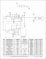
Attached is something I've thrown together. You may already have some of the parts or know better places to get them, but I listed everything just in case (except SW3 since you'll need to see what you need to work with your recorder).
The enclosure and the PCB are suggestions used for another project, so you may want something different. I think the box will allow you to mount the PCB and LCD, but you'll want to verify this before ordering.
I've included an inexpensive programming module. If you're more comfortable, you can purchase a programming cable from PICAXE, but the one I've listed will be cheaper. You can mount the 74C14 circuit to another board to save space on your main circuit. This would also allow you to program other PICAXE's down the road should you have a need for another such project.
I'm not claiming the posted schematic is foolproof, so if you have any questions, let me know.
Attachments
-
 150.4 KB Views: 49
Hi that's brilliant. I will give it a go. I will certainly have the resistors and caps in my bits box. Will check out the others.Attached is something I've thrown together. You may already have some of the parts or know better places to get them, but I listed everything just in case (except SW3 since you'll need to see what you need to work with your recorder).
The enclosure and the PCB are suggestions used for another project, so you may want something different. I think the box will allow you to mount the PCB and LCD, but you'll want to verify this before ordering.
I've included an inexpensive programming module. If you're more comfortable, you can purchase a programming cable from PICAXE, but the one I've listed will be cheaper. You can mount the 74C14 circuit to another board to save space on your main circuit. This would also allow you to program other PICAXE's down the road should you have a need for another such project.
I'm not claiming the posted schematic is foolproof, so if you have any questions, let me know.
Thanks
Ken
Hi I have been reading a bit about PICAXE and it looks very interesting. You say I could go down the route of purchasing a PICAXE cable instead of the 74C14. I think I will probably go this way as I can see other things I could have a go at. Would you recommend I buy a project board instead of building it on strip board?Hi that's brilliant. I will give it a go. I will certainly have the resistors and caps in my bits box. Will check out the others.
Thanks
Ken
macke
If you'd like to use the official PICAXE gear, take a look at the trainer board here. Not cheap, but it includes the programming cable, a breadboard for prototyping, LED's, temp sensor, and more, plus it allows you to connect most (if not all) PICAXE IC's to it. You should be able to prototype most circuits on this, work out the bugs in the program, then build a circuit board and pop the programmed PICAXE onto it.
A less expensive route would be a simple programming board. While you could get one for the 08M2, I'd suggest the one for the 20M2 found here. Why? You can connect the 08M2, 14M2, or the 20M2 to this board since the pinouts are all the same (not the case with the 18M2, so keep that in mind). Just note you'll need to program the PICAXE on the board, move it to your breadboard to test, then back again to make corrections in your program. If you decide to go this route, I suggest replacing the basic 20-pin socket with a ZIF socket like this. This way you won't damage the pins to the PICAXE and insertion and removal will be much quicker.
A less expensive route would be a simple programming board. While you could get one for the 08M2, I'd suggest the one for the 20M2 found here. Why? You can connect the 08M2, 14M2, or the 20M2 to this board since the pinouts are all the same (not the case with the 18M2, so keep that in mind). Just note you'll need to program the PICAXE on the board, move it to your breadboard to test, then back again to make corrections in your program. If you decide to go this route, I suggest replacing the basic 20-pin socket with a ZIF socket like this. This way you won't damage the pins to the PICAXE and insertion and removal will be much quicker.
Hi I will take a look. I am interested in seeing if I can change the ranges from 20 x 20 to 10 x 10 or other grid sizes.If you'd like to use the official PICAXE gear, take a look at the trainer board here. Not cheap, but it includes the programming cable, a breadboard for prototyping, LED's, temp sensor, and more, plus it allows you to connect most (if not all) PICAXE IC's to it. You should be able to prototype most circuits on this, work out the bugs in the program, then build a circuit board and pop the programmed PICAXE onto it.
A less expensive route would be a simple programming board. While you could get one for the 08M2, I'd suggest the one for the 20M2 found here. Why? You can connect the 08M2, 14M2, or the 20M2 to this board since the pinouts are all the same (not the case with the 18M2, so keep that in mind). Just note you'll need to program the PICAXE on the board, move it to your breadboard to test, then back again to make corrections in your program. If you decide to go this route, I suggest replacing the basic 20-pin socket with a ZIF socket like this. This way you won't damage the pins to the PICAXE and insertion and removal will be much quicker.
Macke
Easy to do in software. Alternately, we could add some buttons to the circuit and you can allow the user to change the grid size on the fly. Depending on the number of buttons (dictated by how we design the user interface), we may need to move up to a 14M2 PICAXE. Let me know which way you prefer to go.I am interested in seeing if I can change the ranges from 20 x 20 to 10 x 10 or other grid sizes.
I'm planning to have the program display "column" and "row" and count 20 columns before incrementing one row.
Does this make sense or is there other terminology you use that would make more sense, e.g., X/Y, A/B, etc.?
Hi
On the schematic, if I removed the 74C14 would I need something else to plug the Picaxe cable into. Sorry to be a pain asking all these questions. You are extremely helpful and kind in what you are doing.
macke
Hi yes it would be useful to have 10 x 10, 20 x 20 and 40 x 40 if that's possible. I realise we would need the larger chip, but that would be OK. Re the names, for the individual readings we would like 'Sample No.' instead of column, but 'Row' would be ok for the other one. Also could the Sample No. count only to the end of the row then increment the row by 1 and start again from zero.Easy to do in software. Alternately, we could add some buttons to the circuit and you can allow the user to change the grid size on the fly. Depending on the number of buttons (dictated by how we design the user interface), we may need to move up to a 14M2 PICAXE. Let me know which way you prefer to go.
I'm planning to have the program display "column" and "row" and count 20 columns before incrementing one row.
Does this make sense or is there other terminology you use that would make more sense, e.g., X/Y, A/B, etc.?
On the schematic, if I removed the 74C14 would I need something else to plug the Picaxe cable into. Sorry to be a pain asking all these questions. You are extremely helpful and kind in what you are doing.
macke
Those three only or do you need the ability to change to something else entirely later, e.g., 12 x 37? If only those three, I think we can add one more button and set up the program so that it prompts the user to select one of those three at power up. If we're not concerned with saving the values when turned off, this should be a cinch - no need for a bigger chip or to change the program (on a regular basis anyway).Hi yes it would be useful to have 10 x 10, 20 x 20 and 40 x 40 if that's possible.
Done and done.Re the names, for the individual readings we would like 'Sample No.' instead of column, but 'Row' would be ok for the other one. Also could the Sample No. count only to the end of the row then increment the row by 1 and start again from zero.
Nope, just make sure R1 and R2 is on every PICAXE circuit you make whether the cable is connected or not. Otherwise the PICAXE won't run properly.On the schematic, if I removed the 74C14 would I need something else to plug the Picaxe cable into.
The PICAXE cable has three conductors: serial in, serial out, and GND. Just make those connections and you're good to go. Take a look at page 8 of the first PICAXE manual found here.
Why thank you.You are extremely helpful and kind in what you are doing.
 These are fun projects for me and if I can help someone learn something new and make it a little less intimidating, all the better.
Hate to sound like a di$#, but an arduino Uno R3 with the LCD1602 shield would have taken care of all the hardware and all you would need is a usb cable to program it, plus the LCD1602 shield has plenty of user buttons already (and an SD card socket for data logging later on).... and it would have only cost less than $15.00 US. Just my 2 cents. I like to keep things really simple.
Hi that's
Thank you again
Ken
Hi that's brilliant. Yes we can only see three. Maybe more in the future, but by the time we get there, with your help, I will be proficient in modifying the circuit/software.Those three only or do you need the ability to change to something else entirely later, e.g., 12 x 37? If only those three, I think we can add one more button and set up the program so that it prompts the user to select one of those three at power up. If we're not concerned with saving the values when turned off, this should be a cinch - no need for a bigger chip or to change the program (on a regular basis anyway).
Done and done.
Nope, just make sure R1 and R2 is on every PICAXE circuit you make whether the cable is connected or not. Otherwise the PICAXE won't run properly.
The PICAXE cable has three conductors: serial in, serial out, and GND. Just make those connections and you're good to go. Take a look at page 8 of the first PICAXE manual found here.
Why thank you.
Thank you again
Ken
H
Macke
Hi I did research this, but found it all very confusing. It doesn't come over as very user friendly like picaxe.Hate to sound like a di$#, but an arduino Uno R3 with the LCD1602 shield would have taken care of all the hardware and all you would need is a usb cable to program it, plus the LCD1602 shield has plenty of user buttons already (and an SD card socket for data logging later on).... and it would have only cost less than $15.00 US. Just my 2 cents. I like to keep things really simple.
Macke
Bmorse,Hate to sound like a di$#, but an arduino Uno R3 with the LCD1602 shield would have taken care of all the hardware and all you would need is a usb cable to program it, plus the LCD1602 shield has plenty of user buttons already (and an SD card socket for data logging later on).... and it would have only cost less than $15.00 US. Just my 2 cents. I like to keep things really simple.
Thank you for the information - all the Auduino boards I've ever seen run $25 USD or more, so it's nice to see they can be obtained for much less. I avoid Arduino myself only because they use C to program and C is not an easy language to pick up. The response to that is there are tons of examples which is a sound argument. However, if I'm helping someone, I'd have to put more effort into reverse engineering C code than writing new BASIC code (or simply wish the OP luck in figuring it out themselves), so I often default to recommending something like the PICAXE. I'm not arguing one is better than the other and your suggestion certainly is a worthwhile consideration for the OP.
H
Macke
Hi I have to agree on this one. Most of us have been brought up on BASIC programming. I don't honestly think it would be a huge learning curve to pick it up again. I have done some extensive PASCAL programming in the past. I did dabble in c and c++ but give me basic every time.Bmorse,
Thank you for the information - all the Auduino boards I've ever seen run $25 USD or more, so it's nice to see they can be obtained for much less. I avoid Arduino myself only because they use C to program and C is not an easy language to pick up. The response to that is there are tons of examples which is a sound argument. However, if I'm helping someone, I'd have to put more effort into reverse engineering C code than writing new BASIC code (or simply wish the OP luck in figuring it out themselves), so I often default to recommending something like the PICAXE. I'm not arguing one is better than the other and your suggestion certainly is a worthwhile consideration for the OP.
Macke
Here is some untested code. Use at own risk . . .
Just remove the .txt from the attachment and you'll be able to open it with the PICAXE editor.
The LCD first displays "Select Grid Size" for two seconds then shows:
10 x 10 Grid
R:No T:Yes
If the user presses the reset button, the program selects the 10 x 10 grid. If the user presses the trigger button (on the recorder), the LCD will then show a 20 x 20 grid, then a 40 x 40 grid, then repeat.
We can change the button functions around, i.e., reset button scrolls and trigger button selects, or you can add another button to the 08M2 and avoid using the trigger button on the recorder for the grid selection.
Once a grid selection is made, the program monitors the trigger button and the reset button. The display will show:
Sample No.: 0
Row: 0
If the trigger button is pressed, the LCD will increment the sample number. If the sample number goes above the selected grid size, the row number is incremented once and the sample number is reset to zero.
If at anytime the reset button is pressed, the sample number and row are both reset to zero. We could add another layer of protection against accidental resets by prompting the user to press reset twice to clear the values or using a third button as confirmation. Let me know if you feel this is necessary.
To pick a different grid size, the user will have to turn the PICAXE circuit off then on again. If you add another button, we could add a function so the user doesn't have to cycle power, but I figured that was easiest.
I don't have an AXE133, but I think I have a similar serial LCD module. Let me know if you run into any snafus and I'll see about testing this on my side of the pond.
If you don't need to make this too small, you might consider a 20x4 line LCD like the AXE134Y. This would give you the ability to display the selected grid size at the top and better define the buttons.
Examples:
Select Grid Size
10 x 10 Grid?
No - Press Reset
Yes - Press Trigger
and
Grid Size: 10 x 10
Sample Number: 8
Row: 2
Just a thought - the 16x2 will work just fine though.
Attachments
-
7.8 KB Views: 36
Hi looks really interesting. I think it might be easier to add switches for the different grids. One of our guys suggested using thumb wheel switches.Here is some untested code. Use at own risk . . .
Just remove the .txt from the attachment and you'll be able to open it with the PICAXE editor.
The LCD first displays "Select Grid Size" for two seconds then shows:
10 x 10 Grid
R:No T:Yes
If the user presses the reset button, the program selects the 10 x 10 grid. If the user presses the trigger button (on the recorder), the LCD will then show a 20 x 20 grid, then a 40 x 40 grid, then repeat.
We can change the button functions around, i.e., reset button scrolls and trigger button selects, or you can add another button to the 08M2 and avoid using the trigger button on the recorder for the grid selection.
Once a grid selection is made, the program monitors the trigger button and the reset button. The display will show:
Sample No.: 0
Row: 0
If the trigger button is pressed, the LCD will increment the sample number. If the sample number goes above the selected grid size, the row number is incremented once and the sample number is reset to zero.
If at anytime the reset button is pressed, the sample number and row are both reset to zero. We could add another layer of protection against accidental resets by prompting the user to press reset twice to clear the values or using a third button as confirmation. Let me know if you feel this is necessary.
To pick a different grid size, the user will have to turn the PICAXE circuit off then on again. If you add another button, we could add a function so the user doesn't have to cycle power, but I figured that was easiest.
I don't have an AXE133, but I think I have a similar serial LCD module. Let me know if you run into any snafus and I'll see about testing this on my side of the pond.
If you don't need to make this too small, you might consider a 20x4 line LCD like the AXE134Y. This would give you the ability to display the selected grid size at the top and better define the buttons.
Examples:
Select Grid Size
10 x 10 Grid?
No - Press Reset
Yes - Press Trigger
and
Grid Size: 10 x 10
Sample Number: 8
Row: 2
Just a thought - the 16x2 will work just fine though.
Macke
I think this will complicate the design a bit, but I'll need you to elaborate. What is the goal? Do you want to:I think it might be easier to add switches for the different grids.
- See at a glance what the grid configuration is set to by looking at the position of the switch?
- Make it less complicated for the user to set?
- Be able to change the grid sizes to any combination on the fly, e.g., 12 x 37?
- Something else entirely?
If it is item two, I suggest we change the user interface but continue to use the LCD to select and set the grid size. We can use additional switches, but it will require a larger enclosure depending on the switch(es) used. More importantly, if you use a dedicated switch to select the grid sizes, what does the program do if someone changes the grid size in the middle of a run, either deliberately or accidentally? Reset the count to zero and use the new grid size or ignore the switch until power is cycled, potentially confusing the user? If you use one thumbwheel switch, keep in mind most are 0-9. What happens if we stick with three grid sizes and someone selects 0 or anything above 3?
Item three is more complicated.
Like this?One of our guys suggested using thumb wheel switches.
How many thumbwheel switches - one (for 1-3 grid sizes) or four (two for sample, two for row)? If using thumbwheel switches, we'd either need a very large PICAXE or use an I/O expander IC. Not hard, but then we have the same problems as item two.
Hi would it be possible to have a rotary switch. I am thinking along the lines of a 4 way one for 10 x 10, 20 x 20 and 40 x 40, with the last position being reset or off. I guess it would have to be break before make.I think this will complicate the design a bit, but I'll need you to elaborate. What is the goal? Do you want to:
For item one, do you mean something like a three-position switch where position 1 represents 10 x 10, position 2 represents 20 x 20, and position three represents 40 x 40? I think this would be better accomplished with a larger LCD since you could clearly read the display and not rely on small labels. Perhaps we could have the original 16x2 display to show something like "Sample 1 of 20" and "Row 3 of 20"?
- See at a glance what the grid configuration is set to by looking at the position of the switch?
- Make it less complicated for the user to set?
- Be able to change the grid sizes to any combination on the fly, e.g., 12 x 37?
- Something else entirely?
If it is item two, I suggest we change the user interface but continue to use the LCD to select and set the grid size. We can use additional switches, but it will require a larger enclosure depending on the switch(es) used. More importantly, if you use a dedicated switch to select the grid sizes, what does the program do if someone changes the grid size in the middle of a run, either deliberately or accidentally? Reset the count to zero and use the new grid size or ignore the switch until power is cycled, potentially confusing the user? If you use one thumbwheel switch, keep in mind most are 0-9. What happens if we stick with three grid sizes and someone selects 0 or anything above 3?
Item three is more complicated.
Like this?

How many thumbwheel switches - one (for 1-3 grid sizes) or four (two for sample, two for row)? If using thumbwheel switches, we'd either need a very large PICAXE or use an I/O expander IC. Not hard, but then we have the same problems as item two.
macke
May I ask, again, why?
Setting the switch up as a binary output would be nice, but this would require two inputs which means a bigger PICAXE with more I/O's (pins). We could add resistors to the switch outputs to create voltage dividers then feed all four into the one remaining PICAXE pin which happens to have an ADC input. Reading the voltage on this pin tells us which position the switch is in. Alternately, you could use the ADC function with a 3-way toggle or slide switch. Cheaper relative to a rotary switch, but more probe to accidental switching and a bit harder to determine position from a glance.
Of course, if we're adding the reset function to the rotary switch, we can eliminate the reset push button thereby freeing two pins and can read the switch as binary which simplifies things a little. This would mean the switch would already need to be a BCD switch or you'd need a 4PDT rotary switch.
However, the question remaining is how do you want the program to behave? The simplest option is to reset the count to zero whenever the switch is moved. If we do it this way, you really only need three positions since the count will be reset to zero when a different grid size is chosen.
Hi the reason for co
I am still awaiting input on the final design from one of the guys, but my own personal preference would be as follows.
We would limit the option to just 3 grid sizes 10 x 10, 20 x 20 and 40 x 40. These would be selectable on the rotary switch. At each press of sample button the 'Sample No.' would increment by one. At the end of the row the 'Row No.' would increment by one and the 'Sample No.' would reset to zero. At the end of the grid the 'Sample No.' would retain its count, so say on a 20 x 20 grid the display would show Sample No. 20 Row No 20.
I would look to expand this at a later date when I am more familiar with operation and programming.
macke
Hi the reason for considering a rotary switch is to prevent the operator from accidentally changing the grid setting halfway through a grid.May I ask, again, why?
Setting the switch up as a binary output would be nice, but this would require two inputs which means a bigger PICAXE with more I/O's (pins). We could add resistors to the switch outputs to create voltage dividers then feed all four into the one remaining PICAXE pin which happens to have an ADC input. Reading the voltage on this pin tells us which position the switch is in. Alternately, you could use the ADC function with a 3-way toggle or slide switch. Cheaper relative to a rotary switch, but more probe to accidental switching and a bit harder to determine position from a glance.
Of course, if we're adding the reset function to the rotary switch, we can eliminate the reset push button thereby freeing two pins and can read the switch as binary which simplifies things a little. This would mean the switch would already need to be a BCD switch or you'd need a 4PDT rotary switch.
However, the question remaining is how do you want the program to behave? The simplest option is to reset the count to zero whenever the switch is moved. If we do it this way, you really only need three positions since the count will be reset to zero when a different grid size is chosen.
I am still awaiting input on the final design from one of the guys, but my own personal preference would be as follows.
We would limit the option to just 3 grid sizes 10 x 10, 20 x 20 and 40 x 40. These would be selectable on the rotary switch. At each press of sample button the 'Sample No.' would increment by one. At the end of the row the 'Row No.' would increment by one and the 'Sample No.' would reset to zero. At the end of the grid the 'Sample No.' would retain its count, so say on a 20 x 20 grid the display would show Sample No. 20 Row No 20.
I would look to expand this at a later date when I am more familiar with operation and programming.
macke
| Thread starter | Similar threads | Forum | Replies | Date |
|---|---|---|---|---|
|
|
Logic D | Homework Help | 53 | |
|
|
12hr clock in quartus showing am and pm with switch | Homework Help | 10 | |
|
|
MOD 12 Up Down Counter | Homework Help | 4 | |
| A | counter which increment by +3 | Homework Help | 7 | |
| R | Performing counter increment | Microcontrollers | 3 |


